Rainbow Electronics MAX1717 User Manual
Page 21
MAX1717
Dynamically Adjustable, Synchronous
Step-Down Controller for Notebook CPUs
______________________________________________________________________________________
21
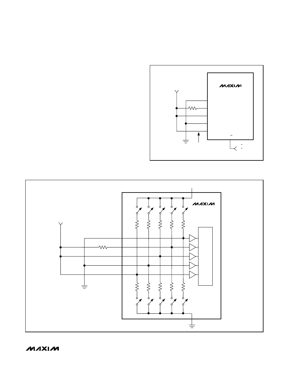
This can be achieved in several ways, including the fol-
lowing two (Figure 10). By using low-impedance pull-up
resistors with the CPU’s VID pins, each pin provides the
low impedance needed for the mux to correctly inter-
pret the B-mode setting. Unfortunately, the low resis-
tances cause several mA additional quiescent current
for each of the CPU’s grounded VID pins. This quies-
cent current can be avoided by taking advantage of the
fact that D0–D4 need only appear low impedance
briefly, not necessarily on a continuous DC basis. High-
impedance pull-ups can also be used if they are
bypassed with a large enough capacitance to make
them appear low impedance for the 4µs sampling inter-
val. As noted in Figure 10, 4.7nF capacitors allow the
inputs to appear low impedance even though they are
pulled up with 1M
Ω resistors.
40k
Ω
D4
D3
D2
D1
D0
40k
Ω
40k
Ω
40k
Ω
40k
Ω
8k
Ω
100k
Ω
8k
Ω
8k
Ω
8k
Ω
8k
Ω
3V TO 5.5V
+5V
B-DATA
LATCH
V
CC
GND
MAX1717
Figure 8. Internal Mux B-Mode Data Test and Latch
MAX1717
D4
D3
D2
D1
D0
A/B
3V TO 5.5V
B-MODE VID =
01000
→ 1.60V
A-MODE VID =
01101
→ 1.35V
100k
Ω
A/B = LOW = 1.60V
A/B = HIGH = 1.35V
Figure 7. Using the Internal Mux with Hard-Wired A-Mode and
B-Mode DAC Codes