Table 4. output voltage vs. dac codes – Rainbow Electronics MAX1717 User Manual
Page 20
MAX1717
Dynamically Adjustable, Synchronous
Step-Down Controller for Notebook CPUs
20
______________________________________________________________________________________
A/
B
Internal Mux
The MAX1717 contains an internal mux that can be used
to select one of two programmed DAC codes and output
voltages. The internal mux is controlled with the A/B pin,
which selects between the A mode and the B mode. In
the A mode, the voltage levels on D0–D4 select the out-
put voltage according to Table 4. Do not leave D0–D4
floating; there are no internal pull-up resistors.
The B mode is programmed by external resistors in
series with D0–D4, using a unique scheme that allows
two sets of data bits using only one set of pins (Figure
7). When A/B goes low (or during power-up with A/B
low), D0–D4 are tested to see if there is a large resis-
tance in series with the pin. If the voltage level on the
pin is a logic low, an internal switch connects the pin to
an internal 40k
Ω pull-up for about 4µs to see if the pin
voltage can be forced high (Figure 8). If the pin voltage
cannot be pulled to a logic high, the pin is considered
low impedance and its B-mode logic state is low. If the
pin can be pulled to a logic high, the impedance is
considered high and so is the B-mode logic state.
Similarly, if the voltage level on the pin is a logic high,
an internal switch connects the pin to an internal 8k
Ω
pull-down to see if the pin voltage can be forced low. If
so, the pin is high-impedance and its B-mode logic
state is high. Otherwise, its logic state is low.
A high pin impedance (and logic high) is 100k
Ω or
greater, and a low impedance (and logic low) is 1k
Ω or
less. The Electrical Characteristics guaranteed levels for
these impedances are 95k
Ω and 1.05kΩ to allow the use
of standard 100k
Ω and 1kΩ resistors with 5% tolerance.
If the output voltage codes are fixed at PC board
design time, program both codes with a simple combi-
nation of pin-strap connections and series resistors
(Figure 7). If the output voltage codes are chosen dur-
ing PC board assembly, both codes can be indepen-
dently programmed with resistors (Figure 9). This
matrix of 10 resistor-footprints can be programmed to all
possible A-mode and B-mode code combinations with
only five resistors.
Often, one or more output-voltage codes are provided
directly by the CPU’s VID pins. If the CPU actively dri-
ves these pins, connect A/B high (A mode) and let the
CPU determine the output voltages. If the B mode is
needed for startup or other reasons, insert resistors in
series with D0–D4 to program the B-mode voltage. Be
sure that the VID pins are actively driven at all times.
If the CPU’s VID pins float, the open-circuit pins can
present a problem for the MAX1717’s internal mux. The
processor’s VID pins can be used for the A-mode set-
ting, together with suitable pull-up resistors. However,
the B-mode VID code is set with resistors in series with
D0–D4, and in order for the B-mode to work, any pins
intended to be B-mode logic low must appear to be low
impedance, at least for the 4µs sampling interval.
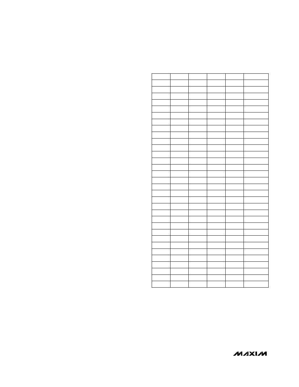
D4
D3
D2
D1
D0
V
OUT
(V)
0
0
0
0
0
2.00
0
0
0
0
1
1.95
0
0
0
1
0
1.90
0
0
0
1
1
1.85
0
0
1
0
0
1.80
0
0
1
0
1
1.75
0
0
1
1
0
1.70
0
0
1
1
1
1.65
0
1
0
0
0
1.60
0
1
0
0
1
1.55
0
1
0
1
0
1.50
0
1
0
1
1
1.45
0
1
1
0
0
1.40
0
1
1
0
1
1.35
0
1
1
1
0
1.30
0
1
1
1
1
No CPU
1
0
0
0
0
1.275
1
0
0
0
1
1.250
1
0
0
1
0
1.225
1
0
0
1
1
1.200
1
0
1
0
0
1.175
1
0
1
0
1
1.150
1
0
1
1
0
1.125
1
0
1
1
1
1.100
1
1
0
0
0
1.075
1
1
0
0
1
1.050
1
1
0
1
0
1.025
1
1
0
1
1
1.000
1
1
1
0
0
0.975
1
1
1
0
1
0.950
1
1
1
1
0
0.925
1
1
1
1
1
No CPU
Table 4. Output Voltage vs. DAC Codes
Note: In the no-CPU state, DH and DL are held low and the
slew-rate controller is set for 0.9V.