6 unpowered mode, 7 high-speed mode – Rainbow Electronics ATA6630 User Manual
Page 16
16
9117C–AUTO–10/09
ATA6628/ATA6630 [Preliminary]
4.6
Unpowered Mode
If you connect battery voltage to the application circuit, the voltage at the VS pin increases
according to the block capacitor (see
). After VS is higher than the VS
undervoltage threshold VS
th
, the IC mode changes from Unpowered Mode to Fail-safe Mode.
The VCC output voltage reaches its nominal value after t
VCC
. This time, t
VCC
, depends on the
VCC capacitor and the load.
The NRES is low for the reset time delay t
reset
. During this time, t
reset
, no mode change is
possible.
IF VS drops below VS
th
, then the IC switches to Unpowered Mode. The behavior of VCC, NRES
and LIN is shown in
. The watchdog needs to be triggered.
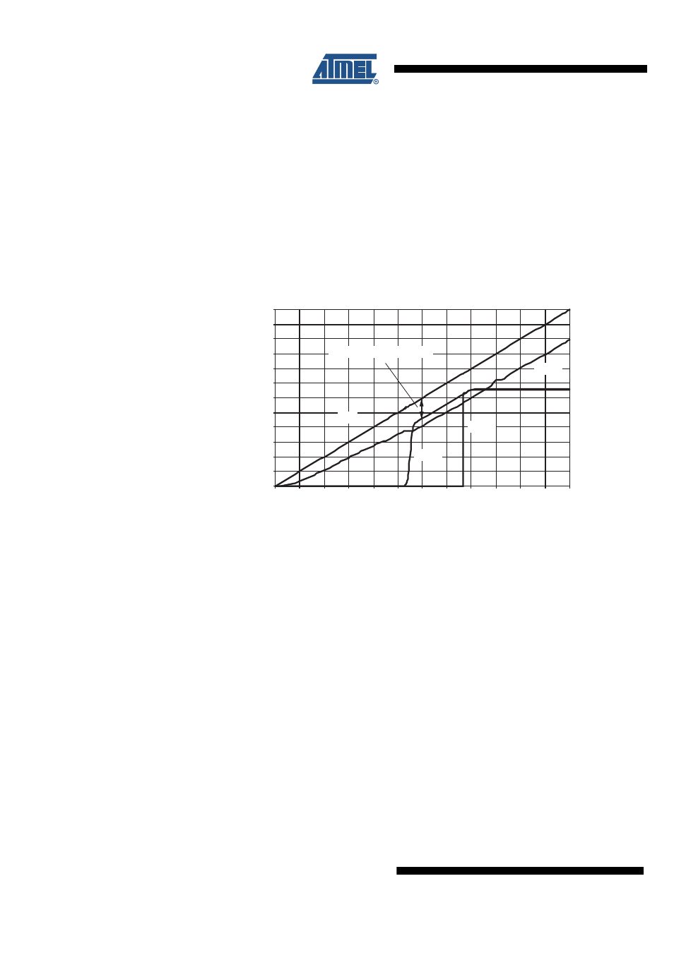
Figure 4-8.
VCC versus VS for the VCC = 3.3V Regulator
4.7
High-speed Mode
If SP_MODE pin is high and the IC is in Normal Mode, the slew rate control is switched off. The
slope time of the LIN falling edge is t
S_Fall
< 2 µs. The slope time of the LIN rising edge strongly
depends on the LIN capacitive and resistive load. To achieve a high baud rate it is recom-
mended to use a small resistor (500
Ω
) and a low capacitor. This allows very fast data
transmission up to 115 kBaud, e.g., for electronic control (ECU) tests and microcontroller pro-
gram or data download. In this mode superior EMC performance is not guaranteed.
0 .0
0 .5
1.0
1.5
2 .0
2 .5
3 .0
3 .5
4 .0
4 .5
5.0
5.5
6 .0
0 .0
0 .5
1.0
1.5
2 .0
2 .5
3 .0
3 .5
4 .0
4 .5
5.0
5.5
6 .0
VS in V
V in V
VCC
LIN
NRES
VS
Regulator drop voltage V
D