2 worst case calculation with rwd_osc = 51 kw, 2 worst case calculation with r, 51 k ω – Rainbow Electronics ATA6624 User Manual
Page 16
16
4986F–AUTO–07/08
ATA6622/ATA6624/ATA6626
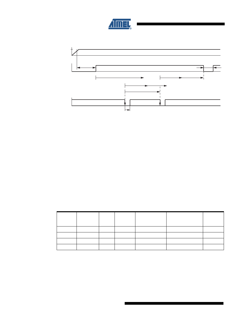
Figure 6-1.
Timing Sequence with R
WD_OSC
= 51 k
Ω
6.2
Worst Case Calculation with R
WD_OSC
= 51 k
Ω
The internal oscillator has a tolerance of 20%. This means that t
1
and t
2
can also vary by 20%.
The worst case calculation for the watchdog period t
wd
is calculated as follows.
The ideal watchdog time t
wd
is between the maximum t
1
and the minimum t
1
plus the minimum
t
2
.
t
1,min
= 0.8
×
t
1
= 16.5 ms, t
1,max
= 1.2
×
t
1
= 24.8 ms
t
2,min
= 0.8
×
t
2
= 17.3 ms, t
2,max
= 1.2
×
t
2
= 26 ms
t
wdmax
= t
1min
+ t
2min
= 16.5 ms + 17.3 ms = 33.8 ms
t
wdmin
= t
1max
= 24.8 ms
t
wd
= 29.3 ms ±4.5 ms (±15%)
A microcontroller with an oscillator tolerance of ±15% is sufficient to supply the trigger inputs
correctly.
t
nres
= 4 ms
Undervoltage Reset
Watchdog Reset
t
reset
= 4 ms
t
trig
> 200 ns
t
1
= 20.6 ms
t
2
= 21 ms
t
2
t
1
t
wd
t
d
= 155 ms
VCC
3.3V/5V
NTRIG
NRES
Table 6-1.
Typical Watchdog Timings
R
WD_OSC
k
Ω
Oscillator
Period
t
osc
/µs
Lead
Time
t
d
/ms
Closed
Window
t
1
/ms
Open Window
t
2
/ms
Trigger Period from
Microcontroller
t
wd
/ms
Reset Time
t
nres
/ms
34
13.3
105
14.0
14.7
19.9
4
51
19.61
154.8
20.64
21.67
29.32
4
91
33.54
264.80
35.32
37.06
50.14
4
120
42.84
338.22
45.11
47.34
64.05
4