4 fail-safe mode, 5 unpowered mode – Rainbow Electronics ATA6624 User Manual
Page 10
10
4986F–AUTO–07/08
ATA6622/ATA6624/ATA6626
The VCC regulator is activated, and the internal LIN slave termination resistor is switched on.
The remote wake-up request is indicated by a low level at the RXD pin to interrupt the microcon-
troller (see
EN high can be used to switch directly from Sleep/Silent to Fail-safe Mode. If EN is still high after
VCC ramp up and undervoltage reset time, the IC switches to the Normal Mode.
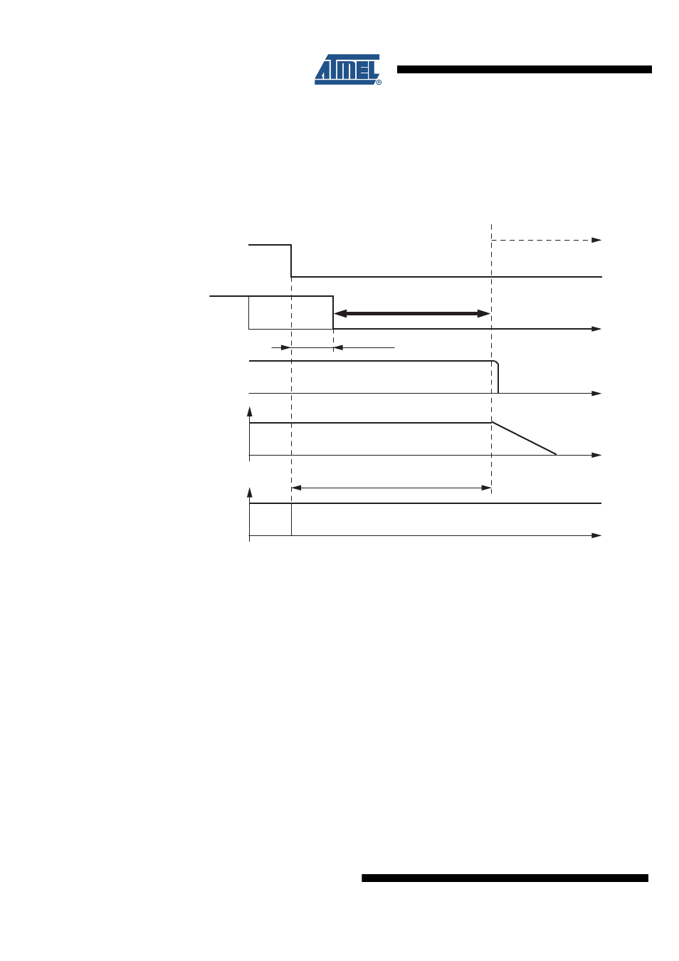
Figure 4-4.
Switch to Sleep Mode
4.4
Fail-safe Mode
The device automatically switches to Fail-safe Mode at system power-up. The voltage regulator
is switched on (VCC = 3.3V/5V/2%/50 mA) (see
). The NRES output
switches to low for t
res
= 4 ms and gives a reset to the microcontroller. LIN communication is
switched off. The IC stays in this mode until EN is switched to high. The IC then changes to Nor-
mal Mode. A power down of V
Batt
(V
S
< 4V) during Silent or Sleep Mode switches the IC into
Fail-safe Mode after power up. A low at NRES switches into Fail-safe Mode directly. During
Fail-safe Mode the TXD pin is an output and signals the last wake-up source.
4.5
Unpowered Mode
If you connect battery voltage to the application circuit, the voltage at the VS pin increases
according to the block capacitor (see
). After VS is higher than the VS
undervoltage threshold VS
th
, the IC mode changes from Unpowered Mode to Fail-safe Mode.
The VCC output voltage reaches its nominal value after t
VCC
. This time, t
VCC
, depends on the
VCC capacitor and the load.
The NRES is low for the reset time delay t
reset
. During this time, t
reset
, no mode change is
possible.
Delay time sleep mode
t
d_sleep
= maximum 20 µs
LIN switches directly to recessive mode
t
d
= 3.2 µs
LIN
VCC
NRES
TXD
EN
Sleep Mode
Normal Mode
Mode select window