Crc generation – Rainbow Electronics DS2432 User Manual
Page 27
PRELIMINARY
DS2432
27 of 30
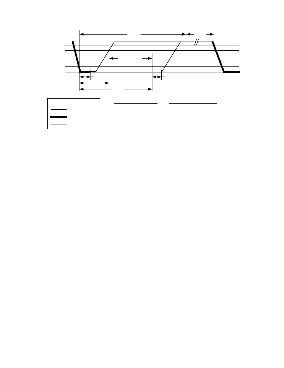
Read-data Time Slot
V
PULLUP
V
IH MIN
V
PULLUP MIN
V
IL MAX
0V
t
LOWR
t
REC
∞
<
≤
REC
t
s
1
µ
s
120
t
s
60
SLOT
µ
µ
<
≤
s
15
t
s
1
LOWR
µ
µ
<
≤
REGULAR SPEED
t
SLOT
MASTER *
SAMPLING
WINDOW
RESISTOR
MASTER
DS2432
Waveform Legend:
t
SU
t
RDV
t
RELEASE
s
45
t
s
0
RELEASE
µ
µ
<
≤
*
s
15
t
RDV
µ
=
s
1
t
SU
µ
<
∞
<
≤
REC
t
s
1
µ
s
16
t
s
6
SLOT
µ
µ
<
≤
s
t
s
1
LOWR
µ
µ
2
<
≤
OVERDRIVE SPEED
s
4
t
s
0
RELEASE
µ
µ
<
≤
*
s
2
t
RDV
µ
=
s
1
t
SU
µ
<
*The optimal sampling point for the master is as close as possible to the end time of the t
RDV
period
without exceeding t
RDV
. For the case of a Read-one time slot, this maximizes the amount of time for the
pull-up resistor to recover the line to a high level. For a Read-zero time slot it ensures that a read will
occur before the fastest 1-Wire device releases the line (t
RELEASE
= 0).
CRC GENERATION
With the DS2432 there are two different types of CRCs (Cyclic Redundancy Checks). One CRC is an
8-bit type. It is computed at the factory and lasered into the most significant byte of the 64-bit ROM. The
equivalent polynomial function of this CRC is X
8
+ X
5
+ X
4
+ 1. To determine whether the ROM data has
been read without error the bus master can compute the CRC value from the first 56 bits of the 64-bit
ROM and compare it to the value read from the DS2432. This 8-bit CRC is received in the true form
(non-inverted) when reading the ROM.
The other CRC is a 16-bit type, generated according to the standardized CRC16-polynomial function
X
16
+ X
15
+ X
2
+ 1. This CRC is used for error detection with the Read Authenticated Page command,
when reading the scratchpad and for fast verification of a data transfer when writing to the scratchpad. It
is the same type of CRC as is used for error detection within the iButton Extended File Structure. In
contrast to the 8-bit CRC, the 16-bit CRC is always returned or sent in the complemented (inverted) form.
A CRC-generator inside the DS2432 chip (Figure 12) will calculate a new 16-bit CRC as shown in the
command flow chart of Figure 7. The bus master may compare the CRC value read from the device to the
one it calculates from the data and decide whether to continue with an operation or to re-read the portion
of the data with the CRC error.
With the Write Scratchpad command the CRC is generated by first clearing the CRC generator and then
shifting in the command code, the Target Addresses TA1 (with T2 to T0 set to 0) and TA2, and all data
bytes as sent by the master. The DS2432 will transmit this CRC only if the scratchpad is filled to its
capacity.