Wire signaling – Rainbow Electronics DS2432 User Manual
Page 25
PRELIMINARY
DS2432
25 of 30
1-WIRE SIGNALING
The DS2432 requires strict protocols to ensure data integrity. The protocol consists of four types of sig-
naling on one line: Reset Sequence with Reset Pulse and Presence Pulse, Write 0, Write 1 and Read Data.
Except for the presence pulse the bus master initiates all these signals. The DS2432 can communicate at
two different speeds, regular speed and Overdrive Speed. If not explicitly set into the Overdrive mode,
the DS2432 will communicate at regular speed. While in Overdrive Mode the fast timing applies to all
waveforms.
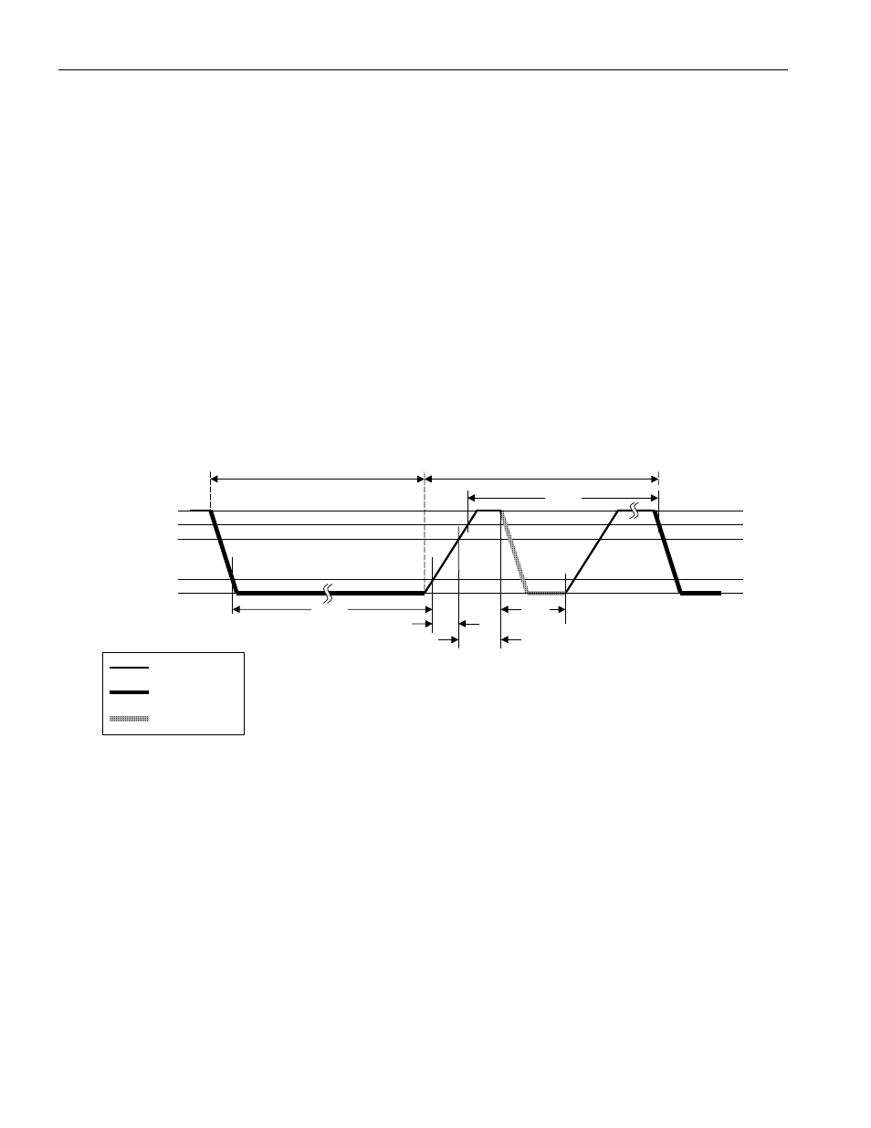
The initialization sequence required to begin any communication with the DS2432 is shown in Figure 10.
A Reset Pulse followed by a Presence Pulse indicates the DS2432 is ready to send or receive data. The
bus master transmits (TX) a reset pulse (t
RSTL
, minimum 480 µs at regular speed, 48 µs at Overdrive
Speed). The bus master then releases the line and goes into receive mode (RX). The 1-Wire bus is pulled
to a high state via the pull-up resistor. After detecting the rising edge on the data pin, the DS2432 waits
(t
PDH
, 15-60 µs at regular speed, 2-6 µs at Overdrive speed) and then transmits the Presence Pulse (t
PDL
,
60-240 µs at regular speed, 8-24 µs at Overdrive Speed). A Reset Pulse of 480 µs or longer will exit the
Overdrive Mode returning the device to regular speed. If the DS2432 is in Overdrive Mode and the Reset
Pulse is no longer than 80 µs the device will remain in Overdrive Mode.
INITIALIZATION PROCEDURE “RESET AND PRESENCE PULSES” Figure 10
V
PULLUP
V
PULLUP MIN
V
IH MIN
V
IL MAX
0V
REGULAR SPEED
480 µs
≤
t
RSTL
<
∞
*
480 µs
≤
t
RSTH
<
∞
**
15
≤
t
PDH
< 60 µs
60 µs
≤
t
PDL
< 240
OVERDRIVE SPEED
48 µs
≤
t
RSTL
< 80 µs
48 µs
≤
t
RSTH
<
∞
**
15
≤
t
PDH
< 6 µs
8 µs
≤
t
PDL
< 24
RESISTOR
MASTER
DS2432
t
R
t
RSTL
t
PDL
t
RSTH
t
PDH
MASTER TX “RESET PULSE” MASTER RX “PRESENCE PULSE”
*
In order not to mask interrupt signaling by other devices on the 1-Wire bus, t
RSTL
+ t
R
should
always be less than 960 µs.
**
Includes recovery time