Overview – Rainbow Electronics DS2432 User Manual
Page 2
PRELIMINARY
DS2432
2 of 30
160-bit message authentication codes (MAC) when reading a memory page or to compute a new secret,
instead of loading it. Applications of the DS2432 include intellectual property security, after-market
management of consumables, and taper proof data carriers.
OVERVIEW
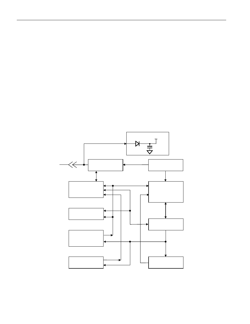
The block diagram in Figure 1 shows the relationships between the major control and memory sections of
the DS2432. The DS2432 has five main data components: 1) 64-bit lasered ROM, 2) 64-bit scratchpad, 3)
four 32-byte pages of EEPROM, 4) 64-bit register page, 5) 64-bit Secrets Memory, and 6) a 512-bit
SHA-1 Engine (SHA = Secure Hash Algorithm). The hierarchical structure of the 1-Wire protocol is
shown in Figure 2. The bus master must first provide one of the seven ROM Function Commands, 1)
Read ROM, 2) Match ROM, 3) Search ROM, 4) Skip ROM, 5) Resume Communication, 6) Overdrive-
Skip ROM or 7) Overdrive-Match ROM. Upon completion of an Overdrive ROM command byte
executed at standard speed, the device will enter Overdrive mode where all subsequent communication
occurs at a higher speed. The protocol required for these ROM function commands is described in Figure
9. After a ROM function command is successfully executed, the memory functions become accessible
and the master may provide any one of the seven memory function commands. The protocol for these
memory function commands is described in Figure 7. All data is read and written least significant bit first.
DS2432 BLOCK DIAGRAM Figure 1
PARASITE POWER
1-Wire net
64-bit
Lasered ROM
1-Wire
Function Control
Secrets Memory
64 bits
64-bit
Scratchpad
Data Memory
4 Pages of
256 bits each
CRC16
Generator
Memory and
SHA Function
Control Unit
512-bit
Secure Hash
Algorithm
Engine
Register Page
64 bits