Rainbow Electronics AT24C1024B User Manual
Page 5
5
AT24C1024B [Preliminary]
5194D–SEEPR–5/07
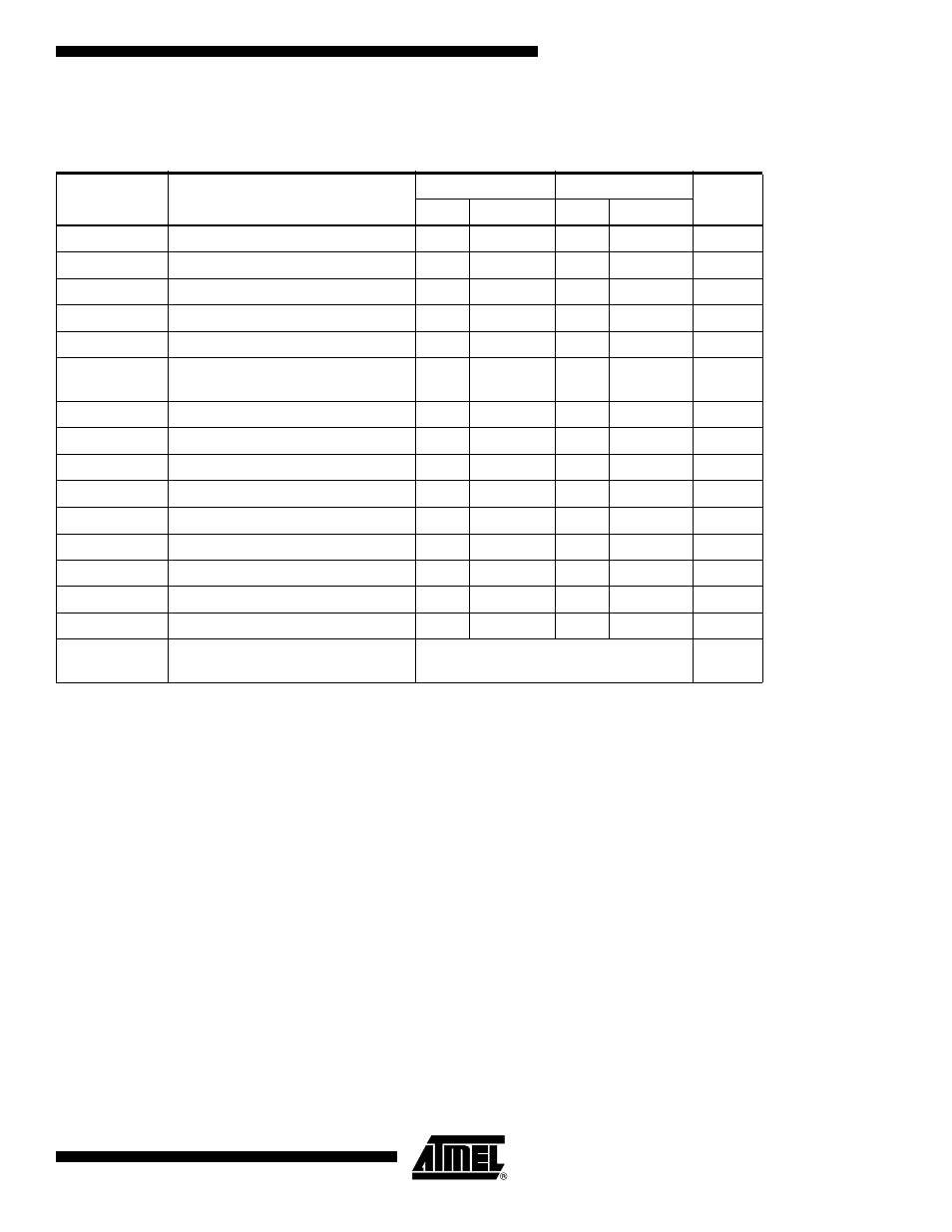
Table 4. AC Characteristics (Industrial Temperature)
Notes: 1. This parameter is ensured by characterization only.
2. AC measurement conditions:
R
L
(connects to V
CC
): 1.3 k
Ω (2.5V, 5V), 10 kΩ (1.8V)
Input pulse voltages: 0.3 V
CC
to 0.7 V
CC
Input rise and fall times:
≤ 50 ns
Input and output timing reference voltages: 0.5 V
CC
Applicable over recommended operating range from T
AI
=
−40°C to +85°C, V
CC
= +1.8V to +3.6V, CL = 100 pF (unless oth-
erwise noted). Test conditions are listed in Note 2.
Symbol
Parameter
1.8-volt
2.5, 5.0-volt
Units
Min
Max
Min
Max
f
SCL
Clock Frequency, SCL
400
1000
kHz
t
LOW
Clock Pulse Width Low
1.3
0.4
µs
t
HIGH
Clock Pulse Width High
0.6
0.4
µs
t
i
Noise Suppression Time
(1)
100
50
ns
t
AA
Clock Low to Data Out Valid
0.05
0.9
0.05
0.55
µs
t
BUF
Time the bus must be free before a
new transmission can start
(1)
1.3
0.5
µs
t
HD.STA
Start Hold Time
0.6
0.25
µs
t
SU.STA
Start Set-up Time
0.6
0.25
µs
t
HD.DAT
Data In Hold Time
0
0
µs
t
SU.DAT
Data In Set-up Time
100
100
ns
t
R
Inputs Rise Time
(1)
0.3
0.3
µs
t
F
Inputs Fall Time
(1)
300
100
ns
t
SU.STO
Stop Set-up Time
0.6
0.25
µs
t
DH
Data Out Hold Time
50
50
ns
t
WR
Write Cycle Time
5
5
ms
Endurance
(1)
25°C, Page Mode, 3.3V
1,000,000
Write
Cycles