Write-data protocol, Read-data protocol, Function command protocol – Rainbow Electronics DS2778 User Manual
Page 43: Table 14. 2-wire protocol key
DS2775/DS2776/DS2777/DS2778
2-Cell, Stand-Alone, Li+ Fuel-Gauge IC with
Protector and Optional SHA-1 Authentication
______________________________________________________________________________________
43
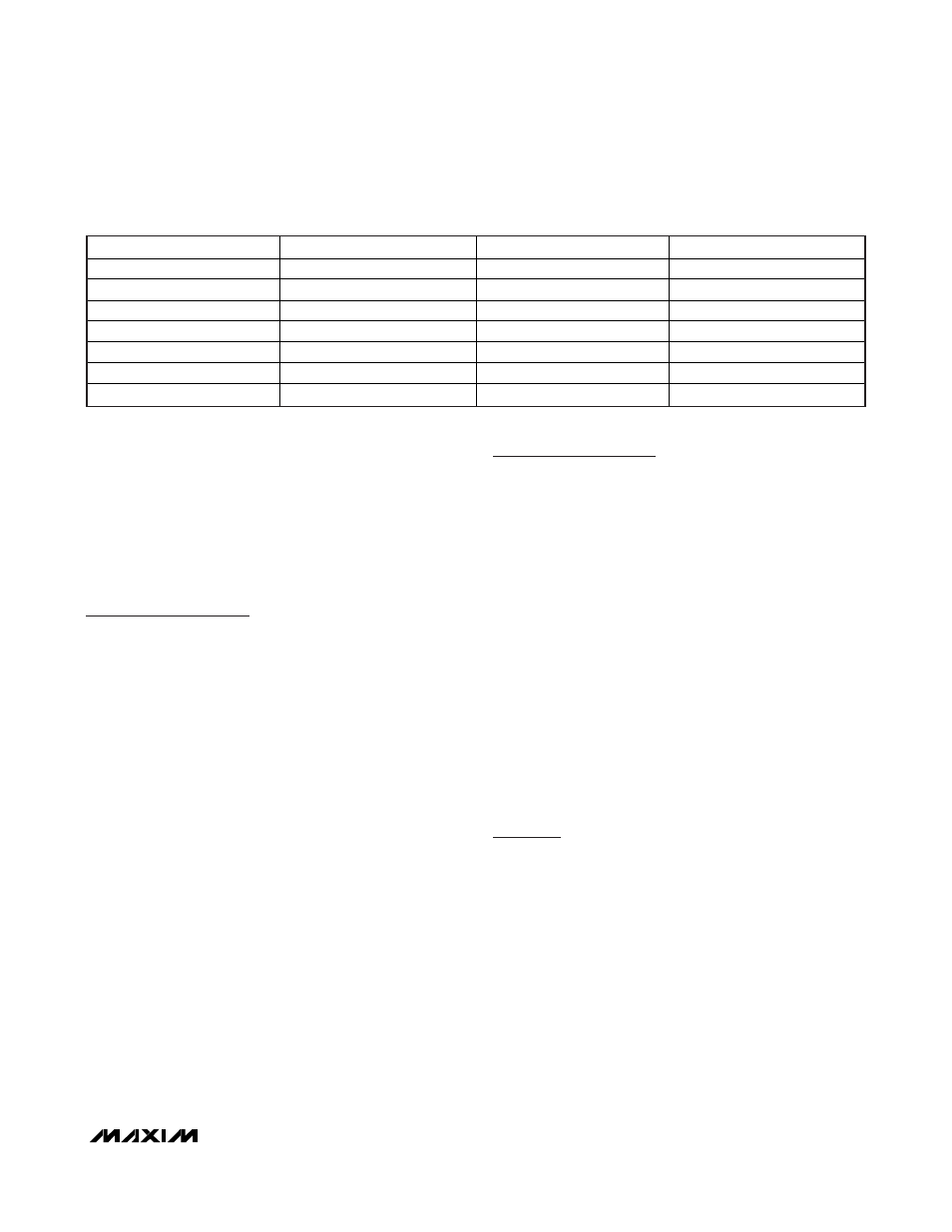
KEY
DESCRIPTION
KEY
DESCRIPTION
S START
Bit
Sr Repeated
START
SAddr Slave
Address
(7-bit)
W
R/
W Bit = 0
FCmd Function
Command
Byte
R
R/
W Bit = 1
MAddr
Memory Address Byte
P
STOP bit
Data
Data Byte Written by Master
Data
Data Byte Returned by Slave
A
Acknowledge Bit (Master)
A
Acknowledge Bit (Slave)
N
Not Acknowledge (Master)
N
Not Acknowledge (Slave)
Table 14. 2-Wire Protocol Key
assumed by the DS2777/DS2778 beginning with the
slave address acknowledge cycle. Control of the SDA
signal is retained by the DS2777/DS2778 throughout
the transaction, except for the acknowledge cycles.
The master indicates the end of a read transaction by
responding to the last byte it requires with a no
acknowledge. This signals the DS2777/DS2778 that
control of SDA is to remain with the master following the
acknowledge clock.
Write-Data Protocol
The write-data protocol is used to write to register and
shadow RAM data to the DS2777/DS2778 starting at
memory address MAddr. Data0 represents the data
written to MAddr, Data1 represents the data written to
MAddr + 1 and DataN represents the last data byte,
written to MAddr + N. The master indicates the end of a
write transaction by sending a STOP or repeated
START after receiving the last acknowledge bit.
S SAddr W A MAddr A Data0 A Data1 A … DataN A P
The MSb of the data to be stored at address MAddr
can be written immediately after the MAddr byte is
acknowledged. Because the address is automatically
incremented after the LSb of each byte is received by
the DS2777/DS2778, the MSb of the data at address
MAddr + 1 is written immediately after the acknowl-
edgement of the data at address MAddr. If the bus
master continues an autoincremented write transaction
beyond address 4Fh, the DS2777/DS2778 ignore the
data. Data is also ignored on writes to read-only
addresses and reserved addresses, locked EEPROM
blocks, as well as a write that auto-increments to the
Function Command register (address FEh). Incomplete
bytes and bytes that are not acknowledged by the
DS2777/DS2778 are not written to memory. As noted in
the
Memory
section, writes to unlocked EEPROM
blocks modify the shadow RAM only.
Read-Data Protocol
The read-data protocol is used to read register and
shadow RAM data from the DS2777/DS2778 starting at
a memory address specified by MAddr. Data0 repre-
sents the data byte in memory location MAddr, Data1
represents the data from MAddr + 1, and DataN repre-
sents the last byte read by the master.
S SAddr W A MAddr A Sr SAddr R A Data0 A Data1 A
… DataN N P
Data is returned beginning with the MSb of the data in
MAddr. Because the address is automatically incre-
mented after the LSb of each byte is returned, the MSb
of the data at address MAddr + 1 is available to the
host immediately after the acknowledgement of the
data at address MAddr. If the bus master continues to
read beyond address FFh, the DS2777/DS2778 output
data values of FFh. Addresses labeled reserved in the
Memory Map
return undefined data. The bus master
terminates the read transaction at any byte boundary
by issuing a not acknowledge followed by a STOP or
repeated START.
Function Command Protocol
The function command protocol executes a device-
specific operation by writing one of the function com-
mand values (FCmd) to memory address FEh. Table 15
lists the DS2777/DS2778 FCmd values and describes
the actions taken by each. A 1-byte write protocol is
used to transmit the function command, with the MAddr
set to FEh and the data byte set to the desired FCmd
value. Additional data bytes are ignored. Data read
from memory address FEh is undefined.
S SAddr W A MAddr = 0FEh A FCmd A P