Li+ protection circuitry, Overvoltage (ov) – Rainbow Electronics DS2778 User Manual
Page 11
DS2775/DS2776/DS2777/DS2778
2-Cell, Stand-Alone, Li+ Fuel-Gauge IC with
Protector and Optional SHA-1 Authentication
______________________________________________________________________________________
11
Li+ Protection Circuitry
During active mode, the DS2775–DS2778 constantly
monitor SNS, V
IN1
, V
IN2
, and PLS to protect the battery
from overvoltage (overcharge), undervoltage (overdis-
charge), and excessive charge and discharge currents
(overcurrent, short circuit). Table 1 summarizes the
conditions that activate the protection circuit, the
response of the DS2775–DS2778, and the thresholds
that release the DS2775–DS2778 from a protection
state. Figure 3 shows Li+ protection circuitry example
waveforms.
Overvoltage (OV)
If either of the voltages on (V
IN2
- V
IN1
) or (V
IN1
- V
SS
)
exceeds the overvoltage threshold, V
OV
, for a period
longer than overvoltage delay, t
OVD
, the CC pin is dri-
ven low to shut off the external charge FET and the OV
flag in the Protection register is set. The DC output
remains high during overvoltage to allow discharging.
When (V
IN2
- V
IN1
) and (V
IN1
- V
SS
) falls below the
charge-enable threshold, V
CE
, the DS2775–DS2778
turn the charge FET on by driving CC high. The
DS2775–DS2778 drive CC high before [(V
IN2
- V
IN1
)
and (V
IN1
- V
SS
)] < V
CE
if a discharge condition per-
sists with V
SNS
≥ 1.2mV and [(V
IN2
- V
IN1
) and (V
IN1
-
V
SS
)] < V
OV
.
ACTIVE
PMOD = 0
UVEN = 0
SLEEP
PSPIO = 0
PSDQ = 0
RISING EDGE ON DQ
CHARGER DETECT
PULL DQ LOW
CHARGER DETECT
ACTIVE
PMOD = 0
UVEN = 1
SLEEP
PSPIO = 0
PSDQ = 1
V
IN1
OR V
IN2
< V
UV
PULL PIO LOW
RISING EDGE ON DQ
CHARGER DETECT
ACTIVE
PMOD = 1
UVEN = 0
SLEEP
PSPIO = 1
PSDQ = 0
PULL DQ LOW FOR t
SLEEP
PULL DQ LOW FOR t
SLEEP
PULL DQ LOW
PULL PIO LOW
CHARGER DETECT
ACTIVE
PMOD = 1
UVEN = 1
SLEEP
PSPIO = 1
PSDQ = 1
V
IN1
OR V
IN2
< V
UV
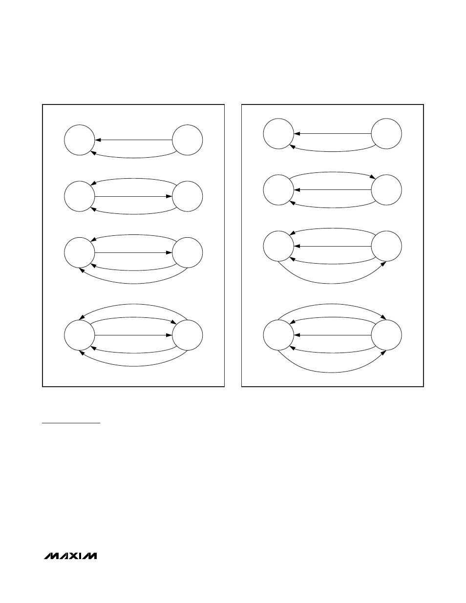
Figure 1. Sleep-Mode State Diagram for DS2775/DS2776
ACTIVE
PMOD = 0
UVEN = 0
SLEEP
PSPIO = 0
PSDQ = X
RISING EDGE ON SDA OR SCL
CHARGER DETECT
V
IN1
OR V
IN2
< V
UV
CHARGER DETECT
ACTIVE
PMOD = 0
UVEN = 1
SLEEP
PSPIO = 0
PSDQ = X
RISING EDGE ON SDA OR SCL
PULL PIO LOW
CHARGER DETECT
PULL SDA AND SCL LOW
FOR t
SLEEP
ACTIVE
PMOD = 1
UVEN = 0
SLEEP
PSPIO = 1
PSDQ = X
RISING EDGE ON SDA OR SCL
PULL SDA AND SCL LOW
FOR t
SLEEP
PULL PIO LOW
CHARGER DETECT
V
IN1
OR V
IN2
< V
UV
ACTIVE
PMOD = 1
UVEN = 1
SLEEP
PSPIO = 1
PSDQ = X
RISING EDGE ON SDA OR SCL
Figure 2. Sleep-Mode State Diagram for DS2777/DS2778