Wire signaling – Rainbow Electronics DS2778 User Manual
Page 39
DS2775/DS2776/DS2777/DS2778
2-Cell, Stand-Alone, Li+ Fuel-Gauge IC with
Protector and Optional SHA-1 Authentication
______________________________________________________________________________________
39
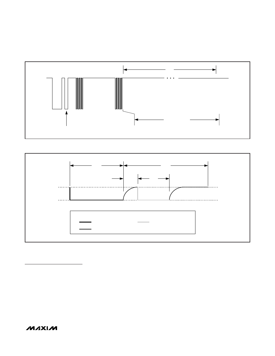
1-Wire Signaling
The 1-Wire bus requires strict signaling protocols to
ensure data integrity. The four protocols used by the
DS2775/DS2776 are as follows: the initialization
sequence (reset pulse followed by presence pulse),
write-zero, write-one, and read data. The bus master
initiates all these types of signaling except the pres-
ence pulse.
Figure 29 shows the initialization sequence required to
begin any communication with the DS2775/DS2776. A
presence pulse following a reset pulse indicates that
the DS2775/DS2776 are ready to accept a Net Address
command. The bus master transmits (Tx) a reset pulse
for t
RSTL
. The bus master then releases the line and
goes into receive mode (Rx). The 1-Wire bus line is
then pulled high by the pullup resistor. After detecting
the rising edge on the DQ pin, the DS2775/DS2776 wait
for t
PDH
and then transmit the presence pulse for t
PDL
.
1-Wire
RESET
SKIP-ROM
COMMAND
CLEAR/LOCK
SECRET COMMAND
OR SET/CLEAR
OVERDRIVE COMMAND
PRESENCE
PULSE
WAIT FOR EEPROM
COPY TIME
t
EEC
Figure 28. Clear/Lock Secret, Set/Clear Overdrive Commands
RESISTOR PULLUP
BUS MASTER ACTIVE LOW
LINE TYPE LEGEND:
DQ
DS2775/DS2776 ACTIVE LOW
PK+
PK-
t
RSTL
t
RSTH
t
PDL
t
PDH
Figure 29. 1-Wire Initialization Sequence