Crc generation, Table 11. secret management function commands – Rainbow Electronics DS2778 User Manual
Page 34
the new secret value to EEPROM. See Figure 26 for
command timing.
Lock Secret [60h]
This command write protects the 64-bit secret to pre-
vent accidental or malicious overwrite of the secret
value. The secret value stored in EEPROM becomes
"final." The host must wait t
EEC
for the DS2776/DS2778
to write the lock secret bit to EEPROM. See Figure 28
for command timing.
1-Wire Bus System
(DS2775/DS2776 Only)
The 1-Wire bus is a system that has a single bus master
and one or more slaves. A multidrop bus is a 1-Wire
bus with multiple slaves, while a single-drop bus has
only one slave device. In all instances, the DS2775/
DS2776 are slave devices. The bus master is typically a
microprocessor in the host system. The discussion of
this bus system consists of five topics: 64-bit net
address, CRC generation, hardware configuration,
transaction sequence, and 1-Wire signaling.
CRC Generation
The DS2775/DS2776 have an 8-bit CRC stored in the
MSB of its 64-bit net address and generates a CRC
during some command protocols. To ensure error-free
transmission of the address, the host system can com-
pute a CRC value from the first 56 bits of the address
and compare it to the CRC from the DS2775/DS2776.
The host system is responsible for verifying the CRC
value and taking action as a result. The DS2775/
DS2776 do not compare CRC values and do not pre-
vent a command sequence from proceeding as a result
of a CRC mismatch. Proper use of the CRC can result
in a communication channel with a very high level of
integrity.
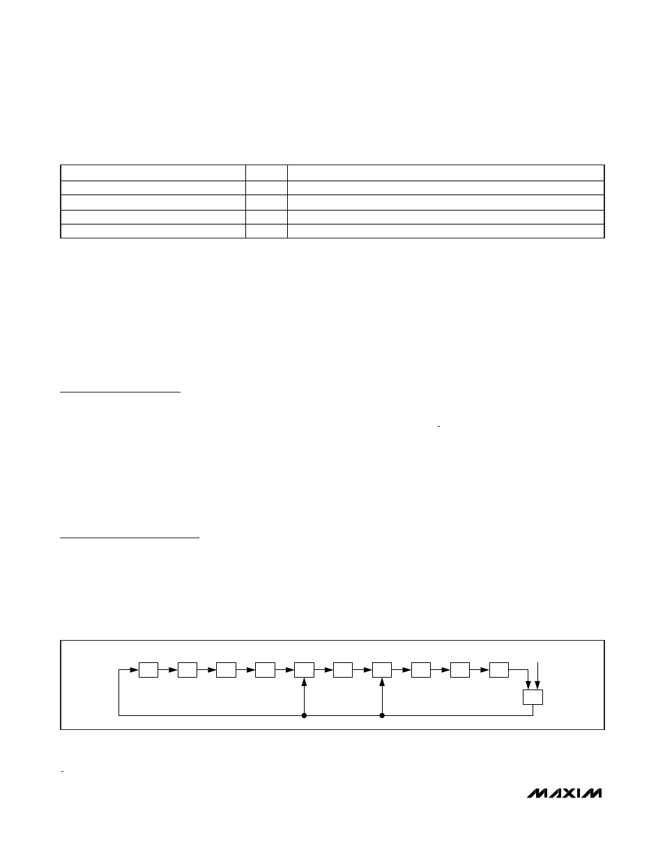
The CRC can be generated by the host using a circuit
consisting of a Shift register and XOR gates as shown
in Figure 23, or it can be generated in software using
the polynomial X
8
+ X
5
+ X
4
+ 1. Additional information
about the Maxim 1-Wire CRC is available in Application
Note 27:
Understanding and Using Cyclic Redundancy
Checks with Maxim iButton
®
Products
.
In the circuit in Figure 23, the Shift register bits are ini-
tialized to 0. Then, starting with the LSb of the family
code, one bit at a time is shifted in. After the 8th bit of
the family code has been entered, then the serial num-
ber is entered. After the 48th bit of the serial number has
been entered, the Shift register contains the CRC value.
During some command sequences, the DS2775/
DS2776 also generate an 8-bit CRC and provide this
value to the bus master to facilitate validation for the
transfer of command, address, and data from the bus
master to the DS2775/DS2776. The DS2775/DS2776
compute an 8-bit CRC for the command and address
bytes received from the bus master for the Read
Memory, Read Status, and Read/Generate CRC com-
mands to confirm that these bytes have been received
correctly. The CRC generator on the DS2775/DS2776 is
DS2775/DS2776/DS2777/DS2778
2-Cell, Stand-Alone, Li+ Fuel-Gauge IC with
Protector and Optional SHA-1 Authentication
34
______________________________________________________________________________________
COMMAND
HEX
FUNCTION
Clear Secret
5Ah
Clears the 64-bit secret to 0000 0000 0000 0000h.
Compute Next Secret without ROM ID
30h
Generates new global secret.
Compute Next Secret with ROM ID
33h
Generates new unique secret.
Lock Secret
60h
Sets lock bit to prevent changes to the secret.
Table 11. Secret Management Function Commands
MSb
XOR
XOR
XOR
INPUT
LSb
Figure 23. 1-Wire CRC Generation Block Diagram
iButton is a registered trademark of Maxim Integrated Products, Inc.