Overcurrent thresholds, Special feature register format, Table 6. coc, doc programmability – Rainbow Electronics DS2778 User Manual
Page 28: Table 7. sc programmability
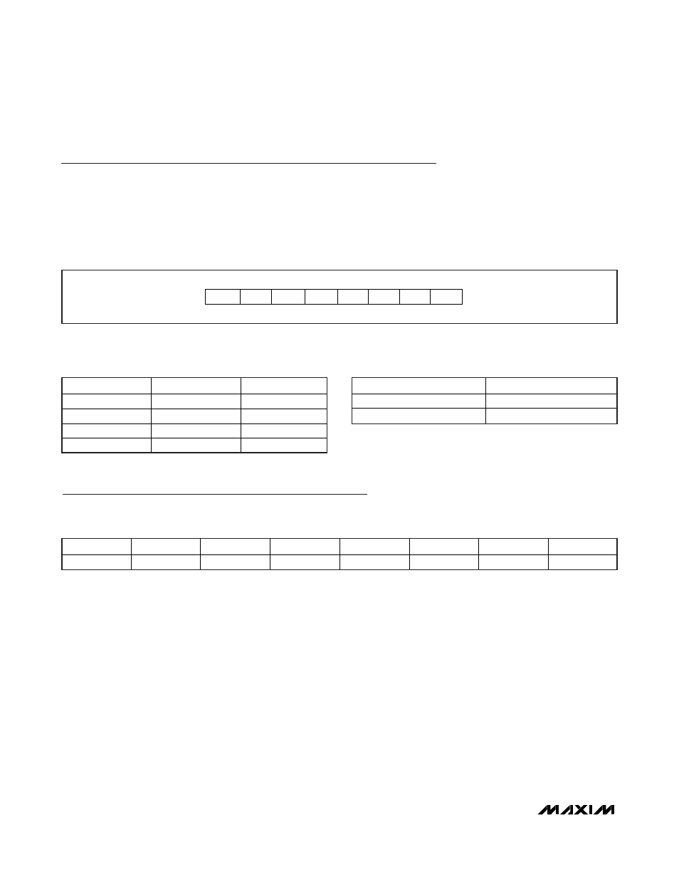
Overcurrent Thresholds
The overcurrent thresholds are set in the upper nibble of the RSGAIN register. The OC1 and OC0 bits set the over-
current thresholds for the charge and discharge thresholds. The short-circuit threshold is set by the SC0 bit (see
Tables 6 and 7, respectively, for overcurrent and short-circuit threshold values). The DS2775–DS2778 have a built-in
fixed delay of t
OCD
for overcurrent events and t
SCD
for short-circuit events. This means that the current ADC must
read a value greater than the overcurrent threshold for longer than t
OCD
and greater than the short-circuit threshold
for longer than t
SCD
before turning off the FET. Overcurrent and short-circuit events less than their respective delays
are ignored.
DS2775/DS2776/DS2777/DS2778
2-Cell, Stand-Alone, Li+ Fuel-Gauge IC with
Protector and Optional SHA-1 Authentication
28
______________________________________________________________________________________
Special Feature Register Format
All register bits are read and write accessible with default values specified in each bit definition.
Special Feature Register (15h)
Bits 7 to 2: Reserved.
Bit 1: SHA Idle Bit (SHA_IDLE). For the DS2777/DS2778, this bit reads logic 1 while an SHA calculation is in
progress and reads logic 0 when the calculation is complete.
Bit 0: PIO Pin Sense and Control Bit (PIOB). Writing a 0 to the PIOB bit activates the PIO pin open-drain output
driver, forcing the PIO pin low. Writing a 1 to PIOB disables the output driver, allowing the PIO pin to be pulled high
or used as an input. Reading PIOB returns the logic level forced on the PIO pin. Note that if the PIO pin is left uncon-
nected with PIOB set, a weak pulldown current source pulls the PIO pin to V
SS
. PIOB is set to a 1 on power-up.
PIOB is also set in sleep mode to ensure the PIO pin is high-impedance in sleep mode. Note: Do not write PIOB to 0
if PSPIO is enabled.
OC[1:0] BIT FIELD
V
COC
(mV)
V
DOC
(mV)
0 0
-25
38
0 1
-38
50
1 0
-50
75
1 1
-75
100
Table 6. COC, DOC Programmability
SC0 BIT FIELD
V
SC
(mV)
0 150
1 300
Table 7. SC Programmability
BIT 7
BIT 6
BIT 5
BIT 4
BIT 3
BIT 2
BIT 1
BIT 0
X X X X X X
SHA_IDLE
PIOB
ADDRESS 78h
X SC0
OC1
OC0 X 2
0
2
-1
2
-2
MSb
LSb
Figure 20. Overcurrent and Short-Circuit Threshold Bits Format