Rainbow Electronics DS2778 User Manual
Page 12
DS2775/DS2776/DS2777/DS2778
2-Cell, Stand-Alone, Li+ Fuel-Gauge IC with
Protector and Optional SHA-1 Authentication
12
______________________________________________________________________________________
ACTIVATION
CONDITION
THRESHOLD DELAY RESPONSE
RELEASE THRESHOLD
Overvoltage (OV) (Note 1)
V
CELL
> V
OV
t
OVD
CC
Off
Both V
CELL
< V
CE
or
(V
SNS
1.2mV and both
V
CELL
< V
OV
) (Note 1)
Undervoltage (UV) (Note 1)
V
CELL
< V
UV
t
UVD
CC Off, DC Off,
Sleep Mode (Note 2)
V
PLS
> V
IN2
(charger connected)
or (both V
CELL
> V
UV
and
UVEN = 0) (Note 3)
Overcurrent, Charge (COC)
V
SNS
< V
COC
t
OCD
CC Off, DC Off
V
PLS
< V
DD
– V
TP
(charger removed) (Note 4)
Overcurrent, Discharge
(DOC)
V
SNS
> V
DOC
t
OCD
DC
Off
V
PLS
> V
DD
– V
TP
(load removed) (Note 5)
Short Circuit (SC)
V
SNS
> V
SC
t
SCD
DC
Off
V
PLS
> V
DD
– V
TP
(Note 5)
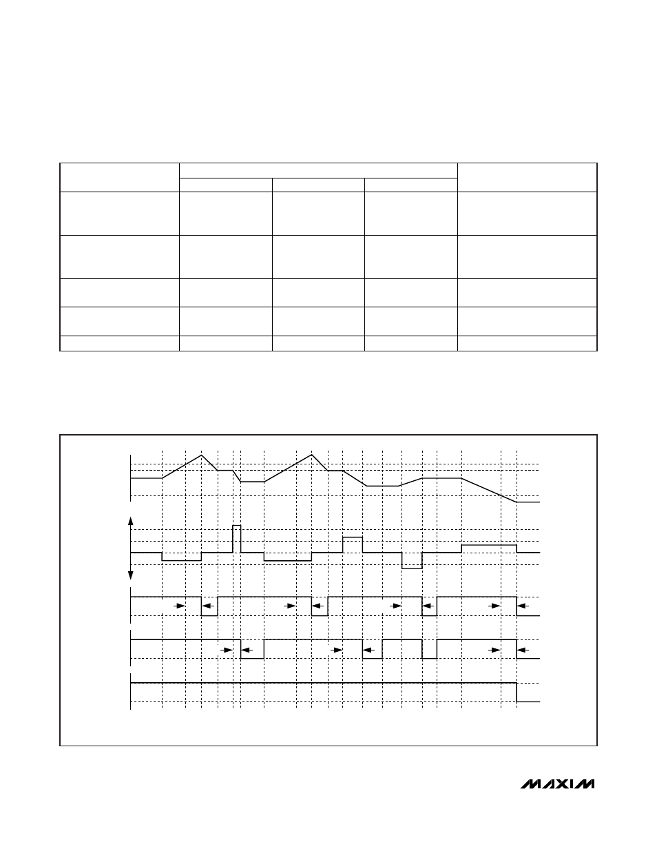
Table 1. Li+ Protection Conditions and DS2775/DS2776 Responses
Note 1: V
CELL
is defined as (V
IN1
- V
SS
) or (V
IN2
- V
IN1
).
Note 2: Sleep mode is only entered if UVEN = 1.
Note 3: If V
CELL
< V
UV
when a charger connection is detected, release is delayed until V
CELL
≥ V
UV
. The recovery charge path pro-
vides an internal current limit (I
RC
) to safely charge the battery.
Note 4: With test current I
PPD
flowing from PLS to V
SS
(pulldown on PLS) enabled.
Note 5: With test current I
TST
flowing from V
DD
to PLS (pullup on PLS).
V
OV
V
CE
V
UV
V
IN
V
SNS
-V
COC
0
V
DOC
V
SC
t
OVD
t
OVD
t
OCD
t
UVD
t
UVD
t
OCD
t
SCO
DISCHARGE
CHARGE
POWER
MODE
ACTIVE
SLEEP*
*IF UVEN = 1.
CC
DC
V
OHCC
V
CP
V
DD
V
CP
V
PLS
Figure 3. Li+ Protection Circuitry Example Waveforms