Voltage measurements – Rainbow Electronics DS2778 User Manual
Page 13
DS2775/DS2776/DS2777/DS2778
2-Cell, Stand-Alone, Li+ Fuel-Gauge IC with
Protector and Optional SHA-1 Authentication
______________________________________________________________________________________
13
Undervoltage (UV)
If the average of the voltages on (V
IN2
- V
IN1
) or
(V
IN1
- V
SS
) drops below the undervoltage threshold,
V
UV
, for a period longer than undervoltage delay, t
UVD
,
the DS2775–DS2778 shut off the charge and discharge
FETs and set the UV flag in the Protection register. If
UVEN is set, the DS2775–DS2778 also enter sleep
mode. When a charger is detected and V
PLS
> V
IN2
,
the DS2775–DS2778 provide a current-limited recovery
charge path (I
RC
) from PLS to V
DD
to gently charge
severely depleted cells. The recovery charge path is
enabled when 0
≤ [(V
IN2
- V
IN1
) and (V
IN1
- V
SS
)] <
V
CE
. The FETs remain off until (V
IN2
- V
IN1
) and
(V
IN1
- V
SS
) exceed V
UV
.
Overcurrent, Charge Direction (COC)
Charge current develops a negative voltage on V
SNS
with respect to V
SS
. If V
SNS
is less than the charge
overcurrent threshold, V
COC
, for a period longer than
overcurrent delay, t
OCD
, the DS2775–DS2778 shut off
both external FETs and set the COC flag in the
Protection register. The charge current path is not re-
established until the voltage on the PLS pin drops
below (V
DD
- V
TP
). The DS2775–DS2778 provide a test
current of value I
PPD
from PLS to V
SS
, pulling PLS
down, in order to detect the removal of the offending
charge current source.
Overcurrent, Discharge Direction (DOC)
Discharge current develops a positive voltage on V
SNS
with respect to V
SS
. If V
SNS
exceeds the discharge
overcurrent threshold, V
DOC
, for a period longer than
t
OCD
, the DS2775–DS2778 shut off the external dis-
charge FET and set the DOC flag in the Protection reg-
ister. The discharge current path is not reestablished
until the voltage on PLS rises above (V
DD
- V
TP
). The
DS2775–DS2778 provide a test current of value I
TST
from V
DD
to PLS, pulling PLS up, in order to detect the
removal of the offending low-impedance load.
Short Circuit (SC)
If V
SNS
exceeds short-circuit threshold, V
SC
, for a
period longer than short-circuit delay, t
SCD
, the
DS2775–DS2778 shut off the external discharge FET
and set the DOC flag in the Protection register. The
discharge current path is not reestablished until the
voltage on PLS rises above (V
DD
- V
TP
). The DS2775–
DS2778 provide a test current of value I
TST
from V
DD
to PLS, pulling PLS up, in order to detect the removal
of the short circuit.
All the protection conditions described are logic
ANDed to affect the CC and DC outputs.
CC = (overvoltage) AND (undervoltage) AND
(overcurrent, charge direction) AND (Protection register
bit CE = 0)
DC = (undervoltage) AND (overcurrent, either direction)
AND (short circuit) AND (Protection register bit
DE = 0)
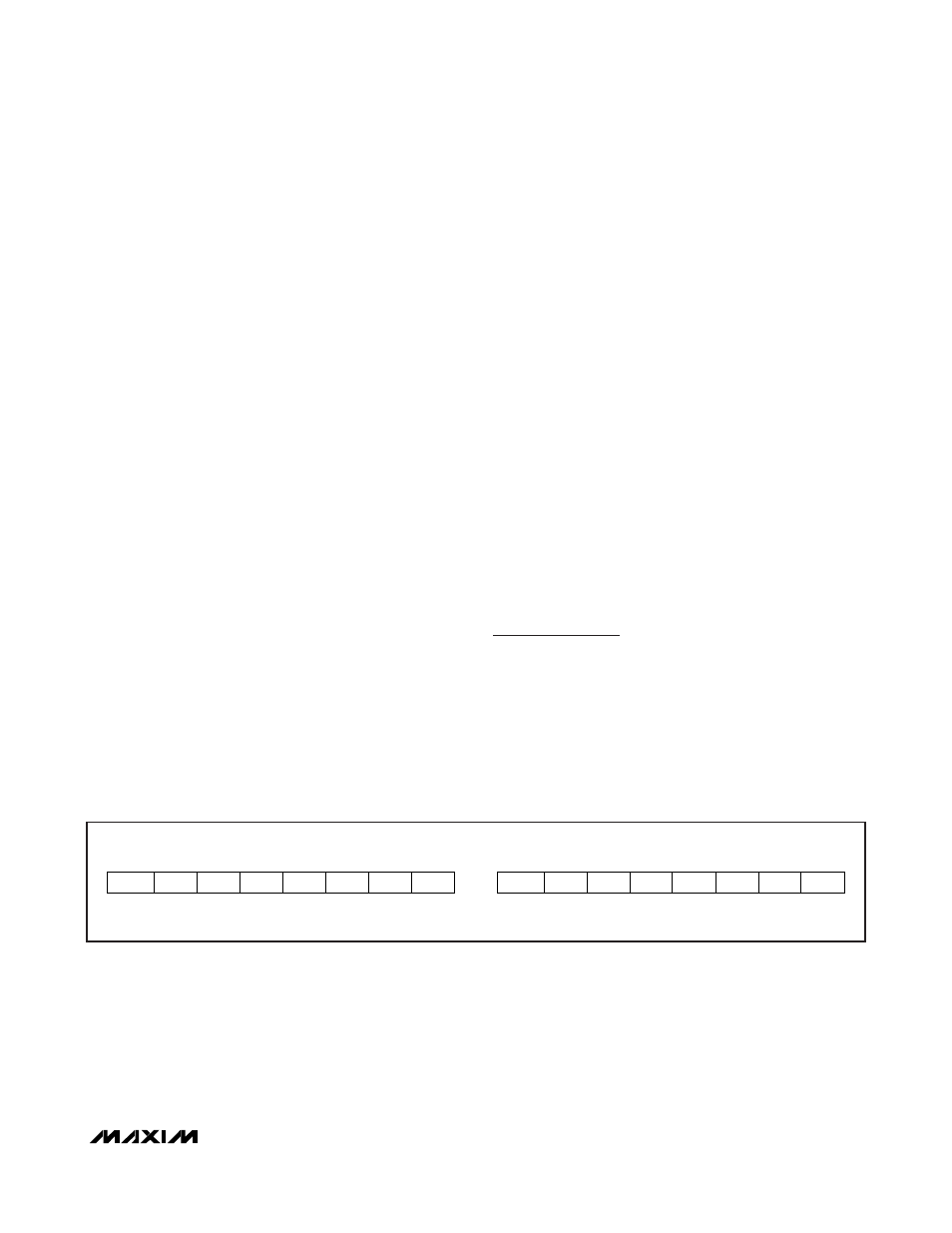
Voltage Measurements
Cell voltages are measured every 440ms. The lowest
potential cell, V
IN1
, is measured with respect to V
SS
.
The highest potential cell, V
IN2
, is measured with
respect to V
IN1
. Battery voltages are measured with a
range of -5V to +4.9951V and a resolution of 4.8828mV
and placed in the Result register in two’s complement
form. Voltages above the maximum register value are
reported as 7FE0h.
MSB - ADDRESS 0Ch, V
IN1
- V
SS
LSB - ADDRESS 0Dh, V
IN1
- V
SS
MSB - ADDRESS 1Ch, V
IN2
- V
IN1
LSB - ADDRESS 1Dh, V
IN2
- V
IN1
S 2
9
2
8
2
7
2
6
2
5
2
4
2
3
2
2
2
1
2
0
X X X X X
MSb
LSb
MSb
LSb
“S”: SIGN BITS(S), “X”: RESERVED
UNITS: 4.883mV
Figure 4. Voltage Register Format