A.c. characteristics, Ht24lc02 – Rainbow Electronics HT24LC02 User Manual
Page 3
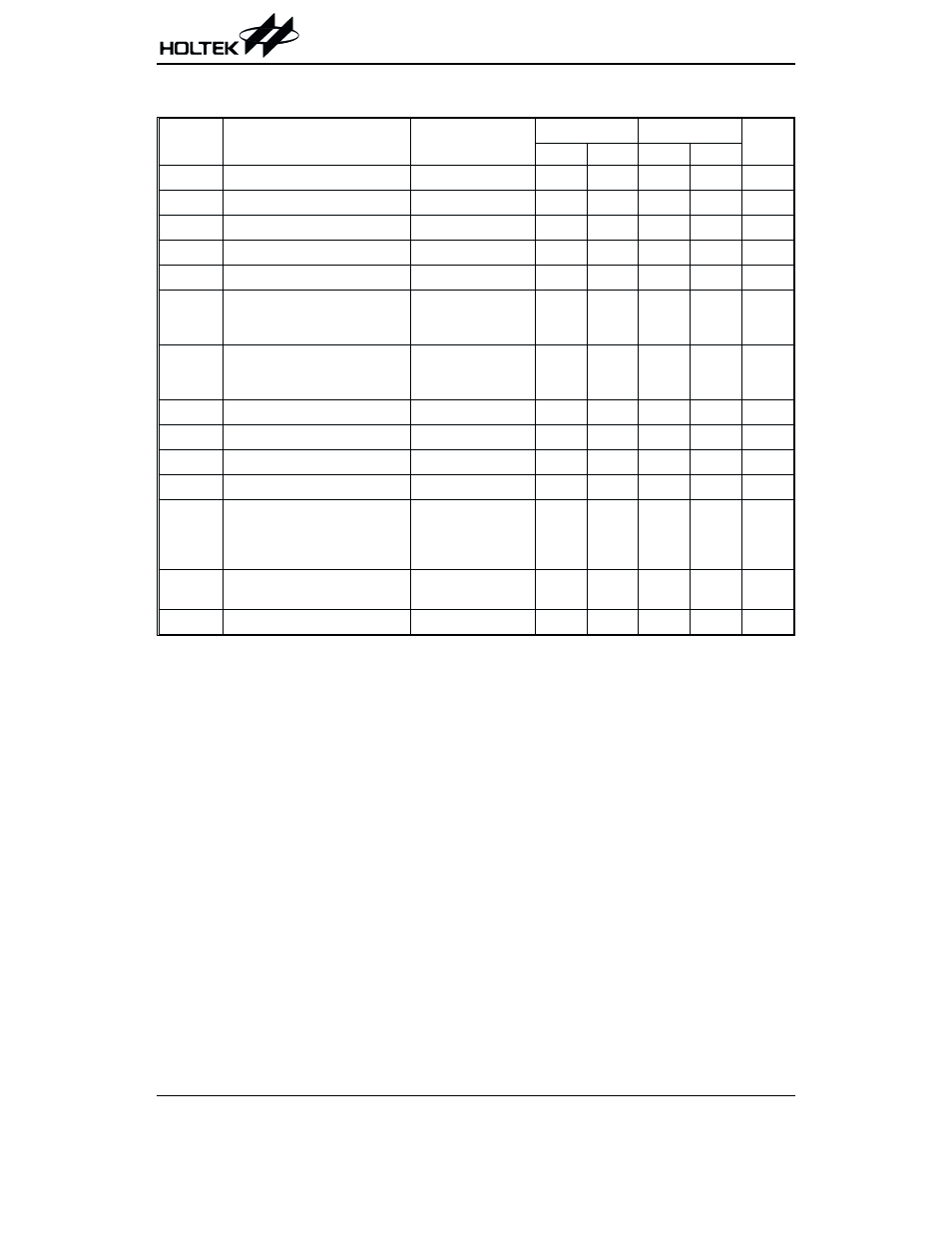
A.C. Characteristics
Ta=0
°C to 70°C
Symbol
Parameter
Remark
Standard Mode*
V
CC
=5V
±10%
Unit
Min.
Max.
Min.
Max.
f
SK
Clock Frequency
¾
¾
100
¾
400
kHz
t
HIGH
Clock High Time
¾
4000
¾
600
¾
ns
t
LOW
Clock Low Time
¾
4700
¾
1200
¾
ns
t
r
SDA and SCL Rise Time
Note
¾
1000
¾
300
ns
t
f
SDA and SCL Fall Time
Note
¾
300
¾
300
ns
t
HD:STA
START Condition Hold Time
After this period the
first clock pulse is
generated
4000
¾
600
¾
ns
t
SU:STA
START Condition Setup Time
Only relevant for
repeated START
condition
4000
¾
600
¾
ns
t
HD:DAT
Data Input Hold Time
¾
0
¾
0
¾
ns
t
SU:DAT
Data Input Setup Time
¾
200
¾
100
¾
ns
t
SU:STO
STOP Condition Setup Time
¾
4000
¾
600
¾
ns
t
AA
Output Valid from Clock
¾
¾
3500
¾
900
ns
t
BUF
Bus Free Time
Time in which the bus
must be free before a
new transmission can
start
4700
¾
1200
¾
ns
t
SP
Input Filter Time Constant
(SDA and SCL Pins)
Noise suppression
time
¾
100
¾
50
ns
t
WR
Write Cycle Time
¾
¾
5
¾
5
ms
Note:
These parameters are periodically sampled but not 100% tested
* The standard mode means V
CC
=2.2V to 5.5V
For relative timing, refer to timing diagrams
HT24LC02
Rev. 1.10
3
November 5, 2002