240q1 – pqfp, At40k/at40klv series fpga, Side view top view bottom view – Rainbow Electronics AT40K40LV User Manual
Page 64
64
AT40K/AT40KLV Series FPGA
0896C–FPGA–04/02
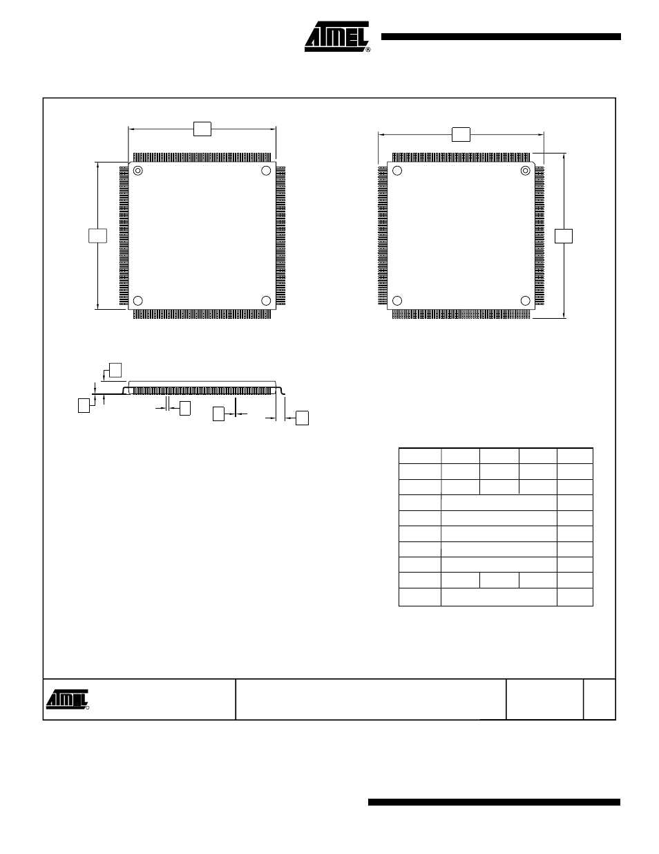
240Q1 – PQFP
2325 Orchard Parkway
San Jose, CA 95131
TITLE
DRAWING NO.
R
REV.
240Q1 A
3/29/02
240Q1, 240-lead, 32 x 32 mm Body, 2.6 Form Opt.,
Plastic Quad Flat Pack (PQFP)
E
D
E1
D1
A2
A1
b
L1
e
Side View
Top View
Bottom View
COMMON DIMENSIONS
(Unit of Measure = mm)
SYMBOL
MIN
NOM
MAX
NOTE
A1
0.25
–
0.50
A2
3.20
3.40
3.60
D
34.60 BSC
3
D1
32.00 BSC
2, 4
E
34.60 BSC
3
E1
32.00 BSC
2, 4
e
0.50 BSC
b
0.17
–
0.27
5
L1
1.30 REF
Notes: 1. This drawing is for general information only. Refer to JEDEC Drawing
MS-029, Variation GA, for additional information.
2. All dimensioning and tolerancing conforms to ASME Y14.5M-1994.
3. To be determined at seating plane.
4. Dimensions D1 and E1 do not include mold protrusions. Allowable
protrusion is 0.25 mm per side. D1 and E1 are maximum plastic body size
dimensions including mold mismatch. Dimensions D1 and E1 shall be
determined at datum plane.
5. Dimension b does not include Dambar protrusion. Allowable Dambar
protrusion shall not cause the lead width to exceed the maximum b
dimension by more than 0.08 mm. Dambar cannot be located on the lower
radius or the foot. The minimum space between protrusion and an adjacent
lead shall not be less than 0.07 mm.