100t1 – tqfp, At40k/at40klv series fpga, Bottom view side view top view – Rainbow Electronics AT40K40LV User Manual
Page 59
59
AT40K/AT40KLV Series FPGA
0896C–FPGA–04/02
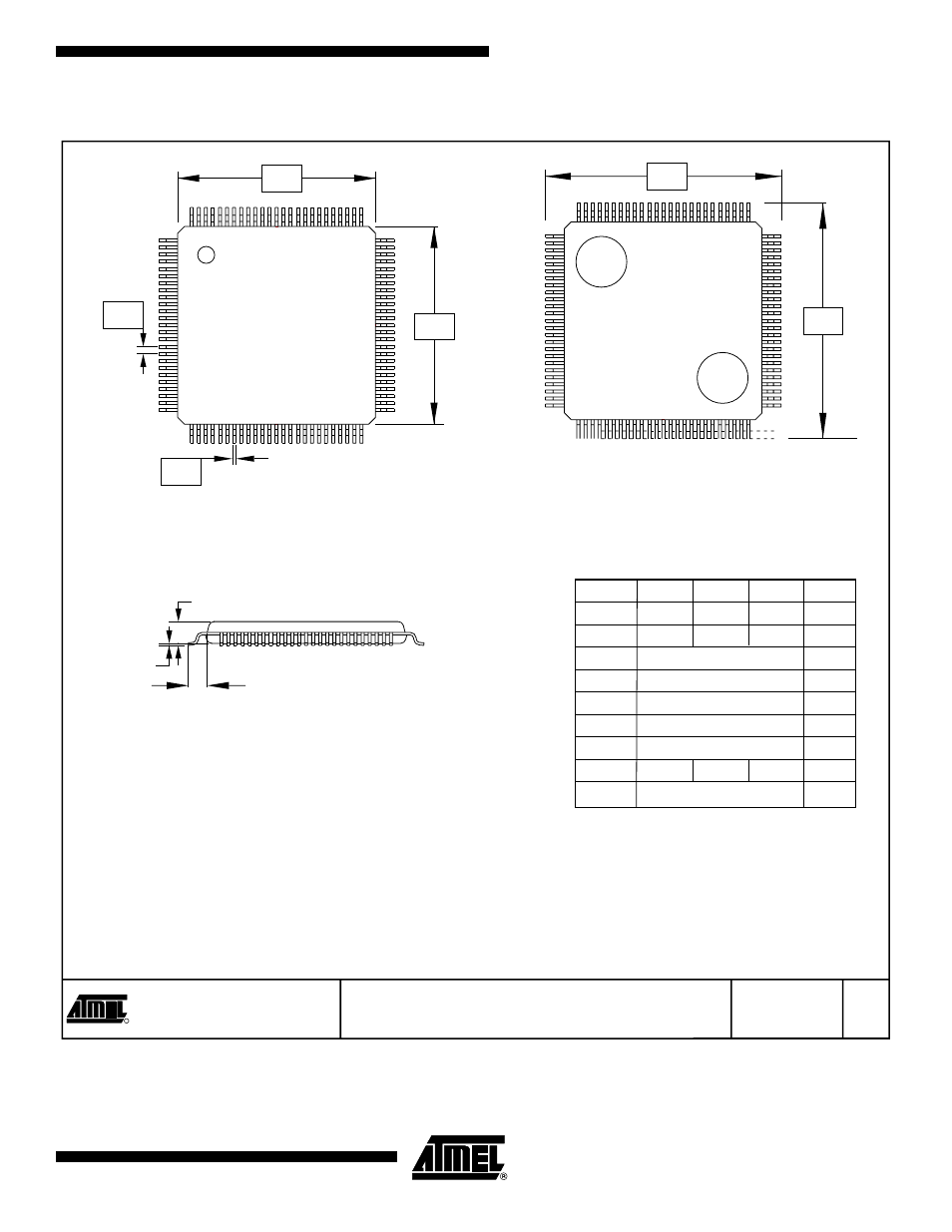
100T1 – TQFP
2325 Orchard Parkway
San Jose, CA 95131
TITLE
DRAWING NO.
R
REV.
100T1
A
11/30/01
A1
A2
Bottom View
Side View
Top View
NT
Y
R
U
C
O
L1
XX
E1
D1
e
E
D
b
Notes: 1. This drawing is for general information only. Refer to JEDEC Drawing MO-153, Variation AA, for proper dimensions, tolerances,
datums, etc.
2. The top package body size may be smaller than the bottom package size by as much as 0.15 mm.
3. Dimensions D1 and E1 do not include mold protrusions. Allowable protrusion is 0.25 mm per side. D1 and E1 are maximum plastic
body size dimensions, including mold mismatch.
4. Dimension b does not include Dambar protrusion. Allowable Dambar protrusion shall not cause the lead width to exceed the maximum
b dimension by more than 0.08 mm. Dambar cannot be located on the lower radius or the foot. Minimum space between protrusion and
an adjacent lead is 0.07 mm for 0.4 and 0.5 mm pitch packages.
5. These dimensions apply to the flat section of the lead between 0.10 mm and 0.25 mm from the lead tip.
6. A1 is defined as the distance from the seating place to the lowest point on the package body.
COMMON DIMENSIONS
(Unit of Measure = mm)
SYMBOL
MIN
NOM
MAX
NOTE
100T1, 100-lead (14 x 14 x 1.0 mm Body), Thin Plastic
Quad Flat Pack (TQFP)
A1
0.05
0.15
6
A2
0.95
1.00
1.05
D
16.00 BSC
D1
14.00 BSC
2, 3
E
16.00 BSC
E1
14.00 BSC
2, 3
e
0.50 BSC
b
0.17
0.22
0.27
4, 5
L1
1.00 REF