4 fail-safe mode, 5 unpowered mode – Rainbow Electronics ATA6625 User Manual
Page 9
9
4957E–AUTO–10/07
ATA6623/ATA6625
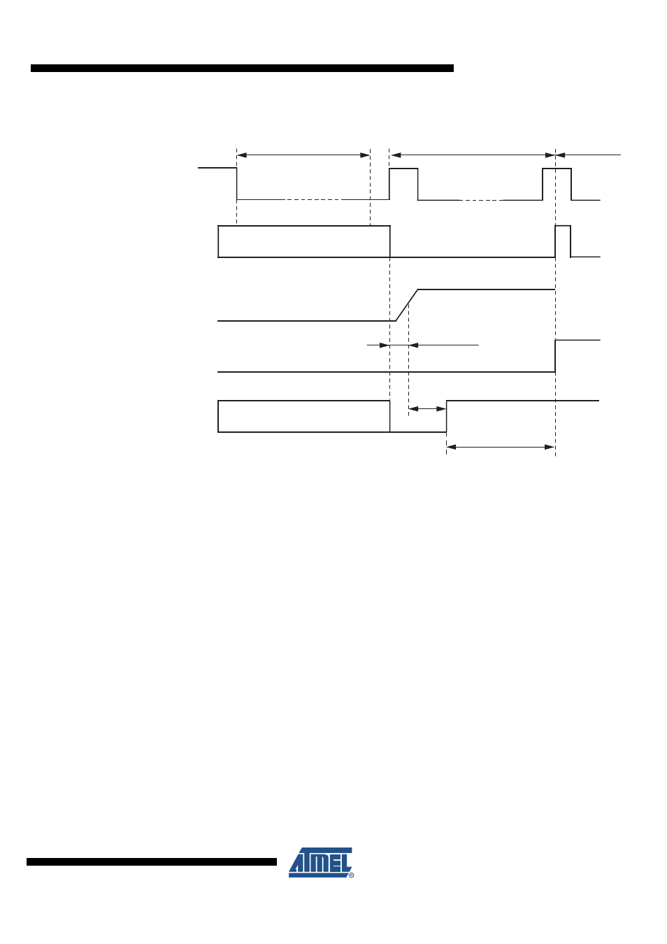
Figure 4-5.
LIN Wake-up Diagram from Sleep Mode
4.4
Fail-safe Mode
At system power-up the device automatically switches to Fail-safe mode. The voltage regulator
is switched on (V
CC
= 3.3V/5V/50 mA), (see
). The NRES output switches
to low for t
res
= 4 ms and gives a reset to the microcontroller. LIN communication is switched off.
The IC stays in this mode until EN is switched to high, and changes then to the Normal mode. A
power down of V
Batt
(V
S
< 4V) during Silent- or Sleep mode switches the IC into the Fail-safe
mode after power up. A logic low at NRES switches the IC into Fail-safe mode directly.
4.5
Unpowered Mode
If you connect battery voltage to the application circuit, the voltage at the VS pin increases
according to the block capacitor (see
). After VS is higher than the VS
undervoltage threshold VS
th
, the IC mode changes from Unpowered mode to Fail-safe mode.
The VCC output voltage reaches its nominal value after t
VCC
. This time, t
VCC
, depends on the
VCC capacitor and the load.
NRES is low for the reset time delay t
Reset
; no mode change is possible during this time.
Regulator wake-up time
Off state
On state
Low
Fail-safe Mode
Normal Mode
EN High
Microcontroller
start-up time delay
Reset
time
Low or floating
Low or floating
NRES
EN
VCC
voltage
regulator
RXD
LIN bus
Bus wake-up filtering time
t
bus