Absolute maximum ratings – Rainbow Electronics ATA6625 User Manual
Page 13
13
4957E–AUTO–10/07
ATA6623/ATA6625
7.
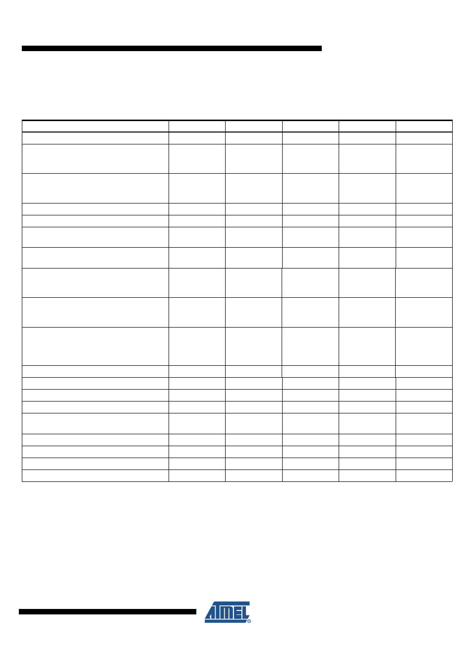
Absolute Maximum Ratings
Stresses beyond those listed under “Absolute Maximum Ratings” may cause permanent damage to the device. This is a stress rating
only and functional operation of the device at these or any other conditions beyond those indicated in the operational sections of this
specification is not implied. Exposure to absolute maximum rating conditions for extended periods may affect device reliability.
Parameters
Symbol
Min.
Typ.
Max.
Unit
Supply voltage V
S
V
S
–0.3
+40
V
Pulse time
≤
500 ms
T
a
= 25°C
Output current I
VCC
≤
50 mA
V
S
+40
V
Pulse time
≤
2 min
T
a
= 25°C
Output current I
VCC
≤
50 mA
V
S
27
V
Logic pins (RxD, TxD, EN, NRES)
–0.3
+5.5
V
Output current NRES
I
NRES
+2
mA
LIN
- DC voltage
–27
+40
V
V
CC
- DC voltage
–0.3
+5.5
V
According to IBEE LIN EMC
Test specification 1.0 following IEC 61000-4-2
- Pin VS, LIN to GND
±6
KV
ESD HBM following STM5.1
with 1.5 k
Ω
/100 pF
- Pin VS, LIN to GND
±8
KV
HBM ESD
ANSI/ESD-STM5.1
JESD22-A114
AEC-Q100 (002)
±3
KV
CDM ESD STM 5.3.1
±750
V
Junction temperature
T
j
–40
+150
°C
Storage temperature
T
s
–55
+150
°C
Operating ambient temperature
T
a
–40
+125
°C
Thermal resistance junction to ambient
(free air)
R
thja
145
K/W
Special heat sink at GND (pin 3) on PCB
R
thja
80
K/W
Thermal shutdown of V
CC
regulator
T
VCCoff
150
160
170
°C
Thermal shutdown of LIN output
T
LINoff
150
160
170
°C
Thermal shutdown hysteresis
T
hys
10
°C