Pin capacitance(1), Dc characteristics(1), Pin capacitanc e – Rainbow Electronics AT25640 User Manual
Page 3: Dc characteristic s
3
AT25080/160/320/640
3260D–SEEPR–9/03
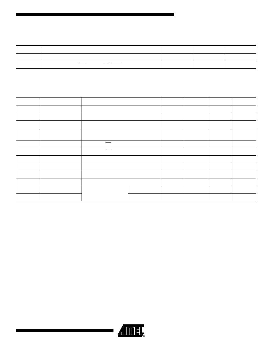
Pin Capacitance
(1)
Note:
1. This parameter is characterized and is not 100% tested.
DC Characteristics
(1)
Note:
1. V
IL
min and V
IH
max are reference only and are not tested.
Applicable over recommended operating range from T
A
= 25
°
C, f = 1.0 MHz, V
CC
= +5.0V (unless otherwise noted).
Symbol
Test Conditions
Max
Units
Conditions
C
OUT
Output Capacitance (SO)
8
pF
V
OUT
= 0V
C
IN
Input Capacitance (CS, SCK, SI, WP, HOLD)
6
pF
V
IN
= 0V
Applicable over recommended operating range from: T
A
= -40
°
C to +125
°
C, V
CC
= +2.7V to +5.5V
Symbol Parameter
Test
Condition
Min
Typ
Max
Units
V
CC1
Supply Voltage
2.7
5.5
V
V
CC2
Supply
Voltage
4.5
5.5
V
I
CC1
Supply
Current
V
CC
= 5.0V at 1 MHz, SO = Open, Read
3.0
mA
I
CC2
Supply
Current
V
CC
= 5.0V at 2 MHz, SO = Open,
Read, Write
5.0
mA
I
SB1
Standby
Current
V
CC
= 2.7V, CS = V
CC
0.2
2.0
µA
I
SB2
Standby Current
V
CC
= 5.0V, CS = V
CC
2.0
5.0
µA
I
IL
Input
Leakage
V
IN
= 0V to V
CC
-3.0
µA
I
OL
Output Leakage
V
IN
= 0V to V
CC
-3.0
3.0
µA
V
IL
(1)
Input Low-voltage
-0.6
V
CC
x 0.3
V
V
IH
(1)
Input High-voltage
V
CC
x 0.7
V
CC
+ 0.5
V
V
OL1
Output
Low-voltage
2.7V
≤
V
CC
≤
5.5V
I
OL
= 3.0 mA
0.4
V
V
OH1
Output High-voltage
I
OH
= -1.6 mA
V
CC
- 0.8
V