Rainbow Electronics MAX16071 User Manual
Page 39
12-Channel/8-Channel, Flash-Configurable System
Managers with Nonvolatile Fault Registers
MAX16070/MAX16071
______________________________________________________________________________________ 39
data register remains at its current value. On the rising
edge of TCK, the controller goes to the shift-DR state if
TMS is low or it goes to the exit1-DR state if TMS is high.
Shift-DR: The test data register selected by the current
instruction connects between TDI and TDO and shifts
data one stage toward its serial output on each rising
edge of TCK while TMS is low. On the rising edge of TCK,
the controller goes to the exit1-DR state if TMS is high.
Exit1-DR: While in this state, a rising edge on TCK puts
the controller in the update-DR state. A rising edge on TCK
with TMS low puts the controller in the pause-DR state.
Pause-DR: Shifting of the test data registers halts while
in this state. All test data registers retain their previous
state. The controller remains in this state while TMS is
low. A rising edge on TCK with TMS high puts the con-
troller in the exit2-DR state.
Exit2-DR: A rising edge on TCK with TMS high while in
this state puts the controller in the update-DR state. A ris-
ing edge on TCK with TMS low enters the shift-DR state.
Update-DR: A falling edge on TCK while in the update-
DR state latches the data from the shift register path of
the test data registers into a set of output latches. This
prevents changes at the parallel output because of
changes in the shift register. On the rising edge of TCK,
the controller goes to the run-test/idle state if TMS is low
or goes to the select-DR-scan state if TMS is high.
Select-IR-Scan: All test data registers retain the previ-
ous states. The instruction register remains unchanged
during this state. With TMS low, a rising edge on TCK
moves the controller into the capture-IR state. TMS high
during a rising edge on TCK puts the controller back into
the test-logic-reset state.
Capture-IR: Use the capture-IR state to load the shift
register in the instruction register with a fixed value. This
value is loaded on the rising edge of TCK. If TMS is high
on the rising edge of TCK, the controller enters the exit1-
IR state. If TMS is low on the rising edge of TCK, the
controller enters the shift-IR state.
Shift-IR: In this state, the shift register in the instruction
register connects between TDI and TDO and shifts data
one stage for every rising edge of TCK toward the TDO
serial output while TMS is low. The parallel outputs of
the instruction register as well as all test data registers
remain at the previous states. A rising edge on TCK with
TMS high moves the controller to the exit1-IR state. A
rising edge on TCK with TMS low keeps the controller in
the shift-IR state while moving data one stage through
the instruction shift register.
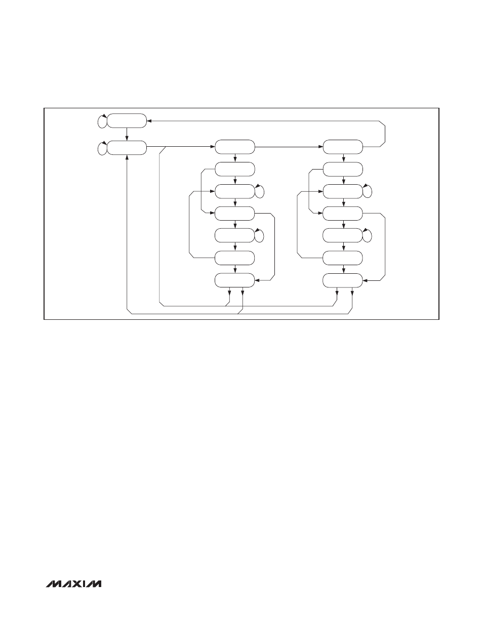
Figure
13. Tap Controller State Diagram
TEST-LOGIC-RESET
1
1
1
1
0
0
RUN-TEST/IDLE
0
0
0
0
1
1
1
0
0
1
0
1
1
0
1
0
1
SELECT-DR-SCAN
SELECT-IR-SCAN
CAPTURE-DR
CAPTURE-IR
SHIFT-DR
SHIFT-IR
EXIT1-DR
EXIT1-IR
PAUSE-DR
PAUSE-IR
EXIT2-DR
EXIT2-IR
UPDATE-DR
UPDATE-IR
0
0
0
0
1
1
0
1
1