Rainbow Electronics MAX16071 User Manual
Page 18
12-Channel/8-Channel, Flash-Configurable System
Managers with Nonvolatile Fault Registers
MAX16070/MAX16071
18 _____________________________________________________________________________________
General-Purpose Inputs/Outputs
GPIO1 to GPIO8 are programmable general-purpose
inputs/outputs. GPIO1–GPIO8 are configurable as a
manual reset input, a watchdog timer input and output,
logic inputs/outputs, fault-dependent outputs. When pro-
grammed as outputs, GPIO_s are open drain or push-
pull. See Tables 8 and 9 for more detailed information on
configuring GPIO1 to GPIO8.
When GPIO1 to GPIO8 are configured as general-pur-
pose inputs/outputs, read values from the GPIO_ ports
through r1Eh and write values to GPIO_s through r3Eh.
Note that r3Eh has a corresponding flash register, which
programs the default state of a general-purpose output.
See Table 7 for more information on reading and writing
to the GPIO_.
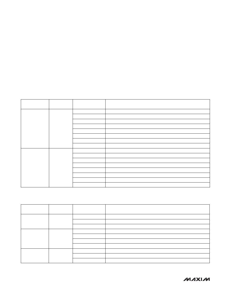
Table
7. GPIO_ State Registers
Table
8. GPIO_ Configuration Registers
REGISTER
ADDRESS
FLASH
ADDRESS
BIT RANGE
DESCRIPTION
1Eh
—
[0]
GPIO1 input state
[1]
GPIO2 input state
[2]
GPIO3 input state
[3]
GPIO4 input state
[4]
GPIO5 input state
[5]
GPIO6 input state
[6]
GPIO7 input state
[7]
GPIO8 input state
3Eh
23Eh
[0]
GPIO1 output state
[1]
GPIO2 output state
[2]
GPIO3 output state
[3]
GPIO4 output state
[4]
GPIO5 output state
[5]
GPIO6 output state
[6]
GPIO7 output state
[7]
GPIO8 output state
REGISTER
ADDRESS
FLASH
ADDRESS
BIT RANGE
DESCRIPTION
3Fh
23Fh
[2:0]
GPIO1 configuration
[5:3]
GPIO2 configuration
[7:6]
GPIO3 configuration (LSB)
40h
240h
[0]
GPIO3 configuration (MSB)
[3:1]
GPIO4 configuration
[6:4]
GPIO5 configuration
[7]
GPIO6 configuration (LSB)
41h
241h
[1:0]
GPIO6 configuration (MSB)
[4:2]
GPIO7 configuration
[7:5]
GPIO8 configuration