Rainbow Electronics MAX16071 User Manual
Page 34
12-Channel/8-Channel, Flash-Configurable System
Managers with Nonvolatile Fault Registers
MAX16070/MAX16071
34 _____________________________________________________________________________________
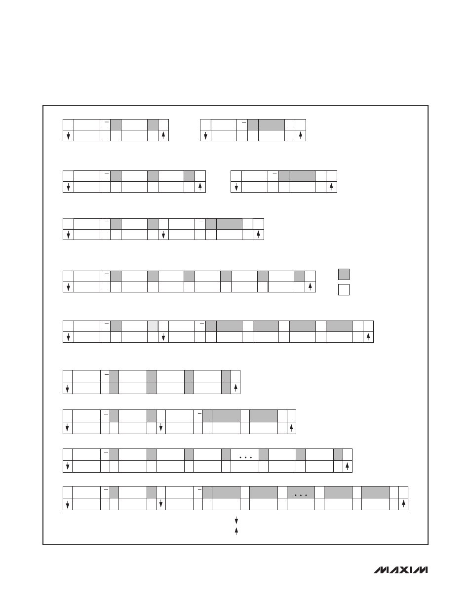
Figure
11. SMBus Protocols
Send Byte Format
S
ADDRESS
Slave Address: Address
of the slave on the serial
interface bus.
Data Byte: Presets the internal
address pointer or represents
a command.
R/W ACK COMMAND ACK
P
7 bits
0
0
0
8 bits
Receive Byte Format
S
ADDRESS
Slave Address: Address
of the slave on the serial
interface bus.
Data Byte: Data is read from
the location pointed to by the
internal address pointer.
R/W ACK
DATA
NACK P
7 bits
1
0
0
1
1
8 bits
Write Byte Format
S
ADDRESS
Slave Address: Address
of the slave on the serial
interface bus.
Command Byte:
Sets the internal
address pointer.
R/W ACK COMMAND ACK
7 bits
0
0
0
0
8 bits
Data Byte: Data is written to
the locations set by the
internal address pointer.
DATA
ACK
P
8 bits
Read Byte Format
S
SLAVE
ADDRESS
Slave Address: Address
of the slave on the serial
interface bus.
Command Byte:
Sets the internal
address pointer.
R/W ACK COMMAND ACK
7 bits
0
0
0
0
1
8 bits
Data Byte: Data is written to
the locations set by the
internal address pointer.
SR
R/W
R/W
R/W
SLAVE
ADDRESS
R/W
7 bits
1
Block Write Format
S
ADDRESS
Slave Address: Address
of the slave on the
serial interface bus.
Command Byte:
FAh
Data Byte: Data is written to the locations
set by the internal address pointer.
ACK COMMAND ACK
7 bits
0
0
0
0
0
0
0
8 bits
BYTE
COUNT = N
ACK
P
8 bits
DATA BYTE 1 ACK
8 bits
DATA BYTE N ACK
8 bits
DATA BYTE … ACK
ACK
DATA BYTE
8 bits
8 bits
SMBALERT#
Alert Response Address:
Only the device that
interrupted the master
responds to this address.
Slave Address: Slave places
its own address on the
serial bus.
S
ADDRESS
R/W ACK
DATA
NACK P
0001100
D.C.
8 bits
NACK P
Slave to master
Master to slave
Block Read Format
S
ADDRESS
Slave Address: Address
of the slave on the
serial interface bus.
S = START Condition
P = STOP Condition
Sr = Repeated START Condition
D.C. = Don’t Care
ACK = Acknowledge, SDA pulled low during rising edge of SCL.
NACK = Not acknowledge, SDA left high during rising edge of SCL.
All data is clocked in/out of the device on rising edges of SCL.
= SDA transitions from high to low during period of SCL.
= SDA transitions from low to high during period of SCL.
Command Byte:
FBh
Data Byte: Data is read from the locations
set by the internal address pointer.
ACK COMMAND ACK
7 bits
ADDRESS
Slave Address: Address
of the slave on the
serial interface bus.
7 bits
0
0
0
0
0
0
0
1
8 bits
ACK
P
8 bits
DATA BYTE N ACK
8 bits
ACK DATA BYTE N
8 bits
DATA BYTE …
NACK
8 bits
SR
ACK
1
BYTE
COUNT = N
S
ADDRESS
COMMAND
A
PEC
P
7 BITS
0
0
8 BITS
0
Write Byte Format with PEC
Read Byte Format with PEC
Block Write with PEC
Block Read with PEC
A
A
DATA
A
0
8 BITS
0
8 BITS
S
S
S
ADDRESS
A
COMMAND
A
DATA
A
PEC
A
P
P
SR
SR
ADDRESS
A
0
0
A
0
1
A
0
A
0
A
0
A
0
A
0
A
0
A
0
A
0
N
P
P
A
0
A
0
A
0
8 BITS
0
0
0
8 BITS
COMMAND
8 BITS
COMMAND
8 BITS
0
A
0
A
0
8 BITS
DATA N
8 BITS
DATA N
8 BITS
PEC
8 BITS
PEC
8 BITS
0
7 BITS
ADDRESS
7 BITS
ADDRESS
7 BITS
1
0
7 BITS
BYTE COUNT N
8 BITS
BYTE COUNT N
8 BITS
ADDRESS
7 BITS
DATA BYTE 1
8 BITS
DATA BYTE 1
8 BITS
DATA BYTE
8 BITS
DATA BYTE
8 BITS
R/W
R/W
R/W
R/W
R/W
R/W