Rainbow Electronics MAX16071 User Manual
Page 13
12-Channel/8-Channel, Flash-Configurable System
Managers with Nonvolatile Fault Registers
MAX16070/MAX16071
______________________________________________________________________________________ 13
Boot-Up Delay
Once EN is above its threshold and the software-enable
bit is set, a boot-up delay occurs before monitoring
begins. This delay is configured in register 77h[3:0] as
shown in Tables 2 and 3.
Internal Current-Sense Amplifier
The current-sense inputs, CSP/CSM, and a current-
sense amplifier facilitate power monitoring (see Figure
4). The voltage on CSP relative to GND is also monitored
by the ADC when the current-sense amplifier is enabled
with r47h[0]. The conversion results are located in regis-
ters r19h and r1Ah (see Table 6). There are two select-
able voltage ranges for CSP set by r47h[1], see Table
4. Although the voltage can be monitored over SMBus
or JTAG, this voltage has no threshold comparators and
cannot trigger any faults. Regarding the current-sense
amplifier, there are four selectable ranges and the ADC
output for a current-sense conversion is:
X
ADC
= (V
SENSE
x A
V
)/1.4V x (2
8
- 1)
where X
ADC
is the 8-bit decimal ADC result in register
r18h, V
SENSE
is V
CSP
- V
CSM,
and A
V
is the current-
sense voltage gain set by r47h[3:2].
In addition, there are two programmable current-sense
trip thresholds: primary overcurrent and secondary over-
current. For fast fault detection, the primary overcurrent
threshold is implemented with an analog comparator
connected to the internal OVERC signal. The OVERC
signal can be output on one of the GPIO_s. See the
General-Purpose Inputs/Outputs section for configur-
ing the GPIO_ to output the OVERC signal. The primary
threshold is set by:
I
TH
= V
CSTH
/R
SENSE
where I
TH
is the current threshold to be set, V
CSTH
is
the threshold set by r47h[3:2], and R
SENSE
is the value
of the sense resistor. See Table 4 for a description of
r47h. OVERC depends only on the primary overcurrent
threshold. The secondary overcurrent threshold is imple-
mented through ADC conversions and digital compari-
son set by r6Ch. The secondary overcurrent threshold
includes programmable time delay options located in
r73h[6:5]. Primary and secondary current-sense faults
are enabled/disabled through r47h[0].
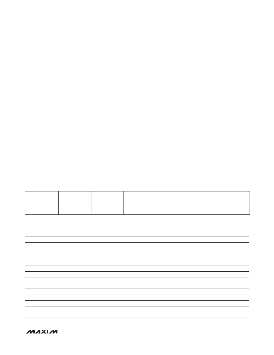
Table 2. Boot-Up Delay Register
Table 3. Boot-Up Delay Values
REGISTER
ADDRESS
FLASH
ADDRESS
BIT RANGE
DESCRIPTION
77h
277h
[3:0]
Boot-up delay
[7:0]
Reserved
CODE
VALUE
0000
25Fs
0001
500Fs
0010
1ms
0011
2ms
0100
3ms
0101
4ms
0110
6ms
0111
8ms
1000
10ms
1001
12ms
1010
25ms
1011
100ms
1100
200ms
1101
400ms
1110
800ms
1111
1.6s