Rainbow Electronics MAX16071 User Manual
Page 21
12-Channel/8-Channel, Flash-Configurable System
Managers with Nonvolatile Fault Registers
MAX16070/MAX16071
______________________________________________________________________________________ 21
ANY_FAULT
GPIO1, GPIO3, GPIO4, GPIO5, and GPIO7 are configu-
rable to assert low during any fault condition.
Overcurrent Comparator (OVERC)
GPIO1 to GPIO8 are configurable to assert low when
the voltage across CSP and CSM exceed the primary
overcurrent threshold. See the Internal Current-Sense
Amplifier section for more details.
Manual Reset (MR)
GPIO1, GPIO3, GPIO5, and GPIO7 are configurable to act
as an active-low manual reset input, MR. Drive MR low to
assert RESET. RESET remains asserted for the selected
reset timeout period after MR transitions from low to high.
Watchdog Input (WDI) and Output (WDO)
GPIO2, GPIO4, GPIO6, and GPIO8 are configurable as
the watchdog timer output, WDO. GPIO1 is configurable
as WDI. See Table 17 for configuration details. WDO is an
active-low output. See the Watchdog Timer section for more
information about the operation of the watchdog timer.
External Fault (EXTFAULT)
GPIO4 and GPIO8 are configurable as the external fault
input/output. When configured as push-pull, EXTFAULT
signals that a critical fault has occurred on one or more
monitored voltages or current. When configured as
open-drain, EXTFAULT can be asserted low by an exter-
nal circuit to trigger a critical fault. This signal can be
used to cascade multiple MAX16070/MAX16071s.
One configuration bit determines the behavior of the
MAX16070/MAX16071 when EXTFAULT is pulled low by
some other device. If register bit r6Dh[2] is set, EXTFAULT
going low triggers a nonvolatile fault log operation.
Faults
The MAX16070/MAX16071 monitor the input (MON_)
channels and compare the results with an overvoltage
threshold, an undervoltage threshold, and a selectable
overvoltage or undervoltage early warning threshold.
Based on these conditions, the MAX16070/MAX16071
assert various fault outputs and save specific informa-
tion about the channel conditions and voltages into the
nonvolatile flash. Once a critical fault event occurs, the
failing channel condition, ADC conversions at the time of
the fault, or both can be saved by configuring the event
logger. The event logger records a single failure in the
internal flash and sets a lock bit that protects the stored
fault data from accidental erasure on a subsequent
power-up.
An overvoltage event occurs when the voltage at a moni-
tored input exceeds the overvoltage threshold for that
input. An undervoltage event occurs when the voltage
at a monitored input falls below the undervoltage thresh-
old. Fault thresholds are set in registers r48h to r6Ch as
shown in Table 11. Disabled inputs are not monitored for
fault conditions and are skipped over by the input mul-
tiplexer. Only the upper 8 bits of a conversion result are
compared with the programmed fault thresholds.
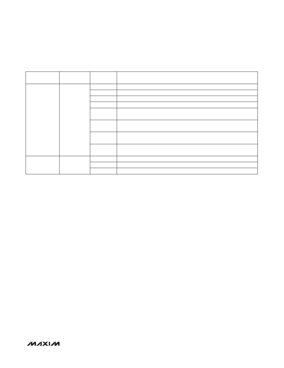
Table
10. Fault1 and Fault2 Dependencies (continued)
REGISTER
ADDRESS
FLASH
ADDRESS
BIT
RANGE
DESCRIPTION
39h
239h
[0]
1 = Fault2 depends on MON9
[1]
1 = Fault2 depends on MON10
[2]
1 = Fault2 depends on MON11
[3]
1 = Fault2 depends on MON12
[4]
1 = Fault2 depends on the overvoltage thresholds of the inputs selected by
r38h and r39h[3:0]
[5]
1 = Fault2 depends on the undervoltage thresholds of the inputs selected by
r38h and r39h[3:0]
[6]
1 = Fault2 depends on the early warning thresholds of the inputs selected by
r38h and r39h[3:0]
[7]
0 = Fault2 is an active-low digital output
1 = Fault2 is an active-high digital output
3Ah
23Ah
[0]
1 = Fault1 depends on secondary overcurrent comparator
[1]
1 = Fault2 depends on secondary overcurrent comparator
[7:2]
Reserved