Rainbow Electronics MAX16071 User Manual
Page 31
12-Channel/8-Channel, Flash-Configurable System
Managers with Nonvolatile Fault Registers
MAX16070/MAX16071
______________________________________________________________________________________ 31
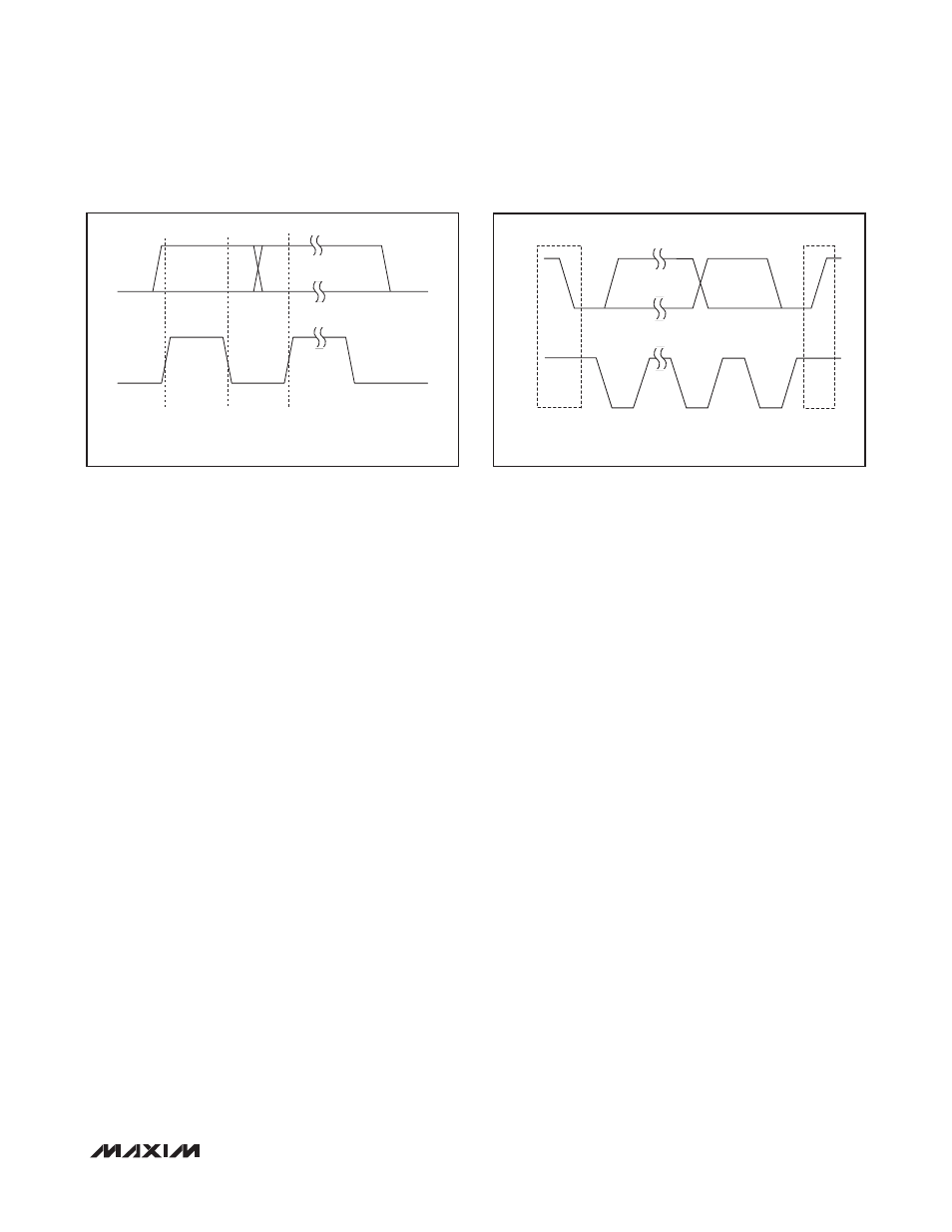
Bit Transfer
Each clock pulse transfers one data bit. The data on
SDA must remain stable while SCL is high (Figure 8);
otherwise the MAX16070/MAX16071 register a START or
STOP condition (Figure 9) from the master. SDA and SCL
idle high when the bus is not busy.
START and STOP Conditions
Both SCL and SDA idle high when the bus is not busy.
A master device signals the beginning of a transmission
with a START condition by transitioning SDA from high to
low while SCL is high. The master device issues a STOP
condition by transitioning SDA from low to high while
SCL is high. A STOP condition frees the bus for another
transmission. The bus remains active if a REPEATED
START condition is generated, such as in the block read
protocol (see Figure 1).
Early STOP Conditions
The MAX16070/MAX16071 recognize a STOP condition
at any point during transmission except if a STOP condi-
tion occurs in the same high pulse as a START condition.
This condition is not a legal SMBus format; at least one
clock pulse must separate any START and STOP condition.
REPEATED START Conditions
A REPEATED START can be sent instead of a STOP
condition to maintain control of the bus during a read
operation. The START and REPEATED START conditions
are functionally identical.
Acknowledge
The acknowledge bit (ACK) is the 9th bit attached to any
8-bit data word. The receiving device always generates
an ACK. The MAX16070/MAX16071 generate an ACK
when receiving an address or data by pulling SDA low
during the 9th clock period (Figure 11). When transmit-
ting data, such as when the master device reads data
back from the MAX16070/MAX16071, the device waits for
the master device to generate an ACK. Monitoring ACK
allows for detection of unsuccessful data transfers. An
unsuccessful data transfer occurs if the receiving device
is busy or if a system fault has occurred. In the event of an
unsuccessful data transfer, the bus master can reattempt
communication at a later time. The MAX16070/MAX16071
generate a NACK after the command byte received dur-
ing a software reboot, while writing to the flash, or when
receiving an illegal memory address.
Slave Address
Use the slave address input, A0, to allow multiple identi-
cal devices to share the same serial bus. Connect A0 to
GND, DBP (or an external supply voltage greater than
2V), SCL, or SDA to set the device address on the bus.
See Table 20 for a listing of all possible 7-bit addresses.
The slave address can also be set to a custom value by
loading the address into register r8Bh[6:0]. See Table
19. If r8Bh[6:0] is loaded with 00h, the address is set by
input A0. Do not set the address to 09h or 7Fh to avoid
address conflicts. The slave address setting takes effect
immediately after writing to the register.
Figure
8. Bit Transfer
Figure
9. START and STOP Conditions
DATA LINE STABLE,
DATA VALID
SDA
SCL
CHANGE OF
DATA ALLOWED
P
S
START
CONDITION
SDA
SCL
STOP
CONDITION