Rainbow Electronics MAX16068 User Manual
Page 36
36 _____________________________________________________________________________________
MAX16068
6-Channel, Flash-Configurable System Manager
with Nonvolatile Fault Registers
Configuring the Device
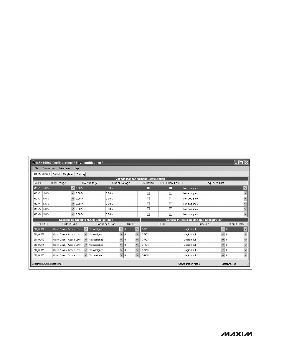
An evaluation kit and a graphical user interface (GUI) are
available to create a custom configuration for the device
(Figure 13).
Refer to the MAX16068 Evaluation Kit for configuration.
Cascading Multiple MAX16068s
Multiple MAX16068s can be cascaded to monitor more
power supplies. There are many ways to cascade the
devices depending on the desired behavior. In general,
there are several techniques as follows:
U
Configure a GPIO on each device to be EXTFAULT
(open drain). Externally wire them together with a sin-
gle pullup resistor. Set register bits r72h[5] and r6Dh[2]
to ‘1’ so that all faults propagate between devices. If a
critical fault occurs on one device, EXTFAULT asserts,
triggering the nonvolatile fault logger in all cascaded
devices and recording a snapshot of all system volt-
ages.
U
Connect open-drain RESET outputs together to obtain
a master system reset signal.
U
Connect all EN inputs together for a master enable
signal.
Layout and Bypassing
Bypass DBP and ABP each with a 1FF ceramic capacitor
to GND. Bypass V
CC
with a 10FF capacitor to ground.
Avoid routing digital return currents through a sensitive
analog area, such as an analog supply input return path
or ABP’s bypass capacitor ground connection. Use
dedicated analog and digital ground planes. Connect
the capacitors as close as possible to the device.
Figure 13. Graphical User Interface Screenshot