Rainbow Electronics MAX16068 User Manual
Page 30
30 _____________________________________________________________________________________
MAX16068
6-Channel, Flash-Configurable System Manager
with Nonvolatile Fault Registers
The block read procedure is the following:
1) The master sends a START condition.
2) The master sends the 7-bit slave address and a
write bit (low).
3) The addressed slave asserts an ACK on SDA.
4) The master sends 8 bits of the block read command
(95h).
5) The slave asserts an ACK on SDA, unless busy.
6) The master generates a REPEATED START condi-
tion.
7) The master sends the 7-bit slave address and a
read bit (high).
8) The slave asserts an ACK on SDA.
9) The slave sends the 8-bit byte count (16).
10) The master asserts an ACK on SDA.
11) The slave sends 8 bits of data.
12) The master asserts an ACK on SDA.
13) Repeat steps 11 and 12 up to fifteen times.
14) The master asserts a NACK on SDA.
15) The master sends a STOP condition.
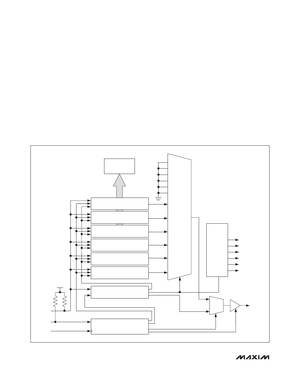
Figure 10. JTAG Block Diagram
TEST ACCESS PORT
(TAP) CONTROLLER
INSTRUCTION REGISTER
[LENGTH = 5 BITS]
BYPASS REGISTER
[LENGTH = 1 BIT]
IDENTIFICATION REGISTER
[LENGTH = 32 BITS]
USER CODE REGISTER
[LENGTH = 32 BITS]
MEMORY ADDRESS REGISTER
[LENGTH = 8 BITS]
MEMORY READ REGISTER
[LENGTH = 8 BITS]
MEMORY WRITE REGISTER
[LENGTH = 8 BITS]
11111
00000
00011
00100
00101
00110
00111
MUX 2
TDO
TDI
TMS
TCK
01000
REGISTERS
AND EEPROM
01001
01010
01011
01100
MUX 1
00111
01000
01001
01010
01011
01100
REBOOT
SAVE
SETUSRFLSH
RSTFLSHADD
RSTUSRFLSH
SETFLSHADD
COMMAND
DECODER
R
PU
V
DB