Applications information – Rainbow Electronics MAX16068 User Manual
Page 35
______________________________________________________________________________________ 35
MAX16068
6-Channel, Flash-Configurable System Manager
with Nonvolatile Fault Registers
Applications Information
Device Behavior at Power-Up
When V
CC
is ramped from 0V, the RESET output is
high impedance until V
CC
reaches 1.4V, at which point
RESET goes low. All other outputs are high impedance
until V
CC
reaches 2.7V, then the flash contents are cop-
ied into register memory. This takes 150Fs (max) after
which the outputs assume their programmed states.
Programming the MAX16068 in Circuit
The MAX16068 can be programmed in the application
circuit by taking into account the following points during
circuit design:
U
The MAX16068 needs to be powered from an inter-
mediate voltage bus or an auxiliary voltage supply so
programming can occur even when the board’s power
supplies are off. This could also be achieved by using
ORing diodes so that power can be provided through
the programming connector.
U
The SMBus or JTAG bus lines should not connect
through a bus multiplexer powered from a voltage rail
controlled by the MAX16068. If the device needs to be
controlled by an on-board FP, consider connecting the
F
P to one bus (such as SMBus) and use the other bus
for in-circuit programming.
Maintaining Power During
a Fault Condition
Power to the MAX16068 must be maintained for a spe-
cific period of time to ensure a successful flash fault
log operation during a fault that removes power to the
circuit. Table 25 shows that the amount of time required
depends on the settings in the fault control register
(r6Dh[1:0]).
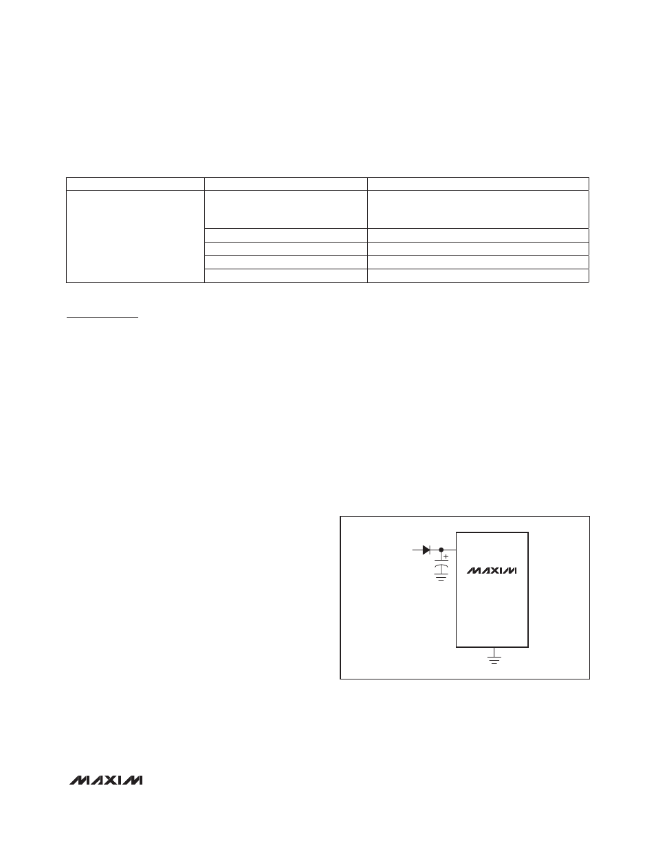
Maintain power for shutdown during fault conditions in
applications where the always-on power supply cannot
be relied upon by placing a diode and a large capacitor
between the voltage source, V
IN
, and V
CC
(Figure 12).
The capacitor value depends on V
IN
and the time delay
required, t
FAULT_SAVE
. Use the following formula to cal-
culate the capacitor size:
C = (t
FAULT_SAVE
x I
CC(MAX)
)/(V
IN
- V
DIODE
- V
UVLO
)
where the capacitance is in Farads and t
FAULT_SAVE
is in
seconds, I
CC(MAX)
is 14mA, V
DIODE
is the voltage drop
across the diode, and V
UVLO
is 2.7V. For example, with
a V
IN
of 14V, a diode drop of 0.7V, and a t
FAULT_SAVE
of 153ns, the minimum required capacitance is 202FF.
Table 25. RESET State, Flash State, and Reset Reason
Figure 12. Power Circuit for Shutdown During Fault Conditions
REGISTER ADDRESS
BIT RANGE
DESCRIPTION
r20h
[0]
Reset output state
0 = RESET is low
1 = RESET is high
[1]
1 = Flash memory is busy
[2]
1 = Last reset asserted due to EN going low
[3]
1 = Last reset asserted due to watchdog timeout
[7:4]
Not used
MAX16068
V
CC
C
V
IN
GND