Rainbow Electronics MAX16068 User Manual
Page 26
26 _____________________________________________________________________________________
MAX16068
6-Channel, Flash-Configurable System Manager
with Nonvolatile Fault Registers
Packet Error Checking (PEC)
The MAX16068 features a packet-error checking (PEC)
mode that is useful to improve the reliability of the com-
munication bus by detecting bit errors. By enabling PEC,
an extra CRC-8 error check byte is added in the data
string during each read and/or write sequence. Enable
PEC by writing a ‘1’ to r8Bh[7].
The CRC-8 byte is calculated using the polynomial:
C = X
8
+ X
2
+ X + 1
The PEC calculation includes all bytes in the transmis-
sion, including address, command and data. The PEC
calculation does not include ACK, NACK, START, STOP,
or REPEATED START.
Command Codes
The MAX16068 uses eight command codes for block
read, block write, and other commands. See Table 20
for a list of command codes.
To initiate a software reboot, send A7h using the send
byte format. A software-initiated reboot is function-
ally the same as a hardware-initiated power-on reset.
During boot-up, flash configuration data in the range
of 230h–28Ch is copied to r30h–r8Ch registers in the
default page.
Send command code A8h to trigger a fault store to flash.
Configure the Critical Fault Log Control register (6Dh) to
store ADC conversion results and/or fault flags.
While in the flash page, send command code A9h to
access the flash page (addresses from 200h–2FFh).
Once command code A9h has been sent, all addresses
are recognized as flash addresses only. Send command
code AAh to return to the default page (addresses from
000h–0FFh). Send command code ABh to access the
user flash-page (addresses from 300h–3FFh), and send
command code ACh to return to the flash page.
Restrictions When Writing to Flash
Flash must be written to 8 bytes at a time. The initial
address must be aligned to 8-byte boundaries—the 3
LSBs of the initial address must be ‘000’. Write the 8
bytes using a single block write command or using eight
successive Write Byte commands. A write operation
requires 122ms for each 8-byte block. After program-
ming a block, check r20h[1] (see Table 25) to make sure
the write operation is complete before attempting to write
the next block.
Table 20. Command Codes
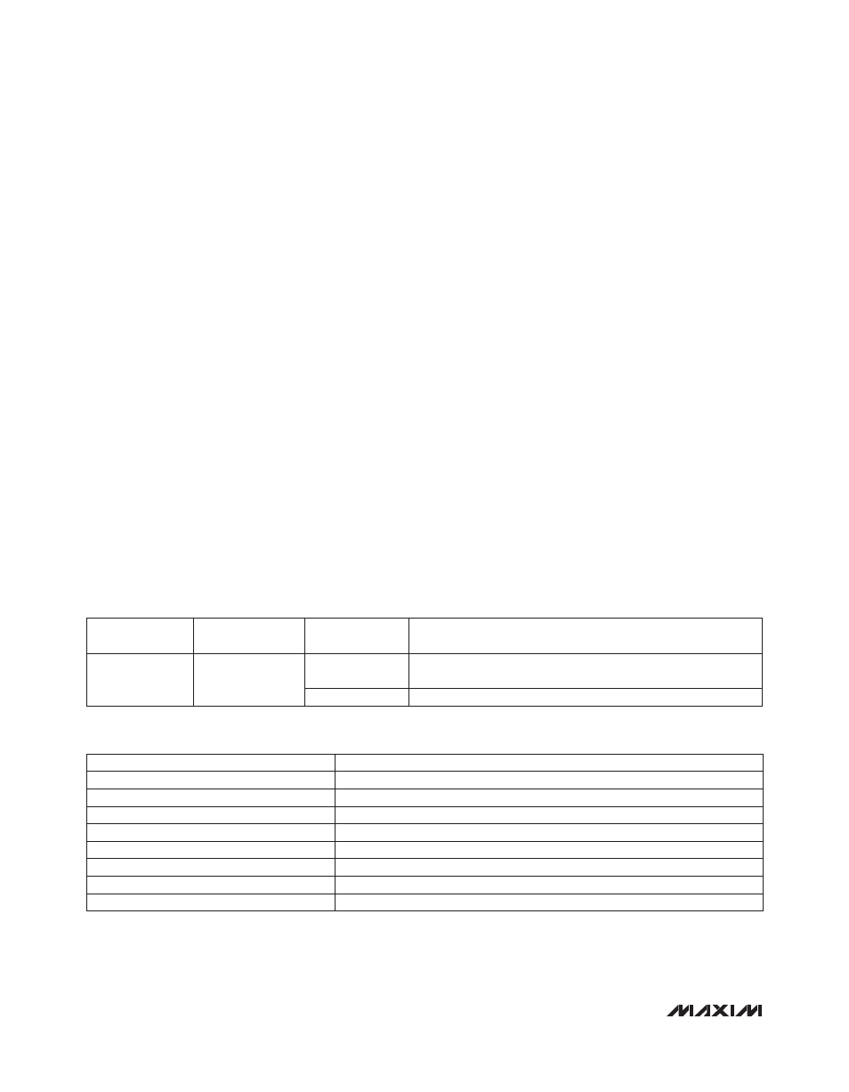
Table 19. SMBus Settings Register
COMMAND CODE
ACTION
A5h
Block write
A6h
Block read
A7h
Reboot flash in register file
A8h
Trigger emergency save to flash
A9h
Flash page access ON
AAh
Flash page access OFF
ABh
User flash access ON (must be in flash page already)
ACh
User flash access OFF (return to flash page)
REGISTER
ADDRESS
FLASH
ADDRESS
BIT RANGE
DESCRIPTION
8Bh
28Bh
[6:0]
SMBus Slave Address Register. Set to 00h to use A0 pin address
setting.
[7]
1 = Enable PEC (Packet Error Check).