Table 1. component values – Rainbow Electronics MAX19996A User Manual
Page 32
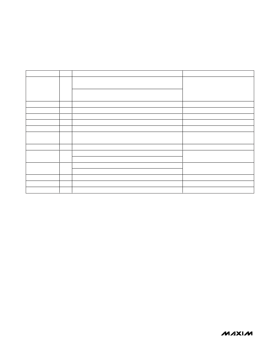
DESIGNATION
QTY
DESCRIPTION
COMPONENT SUPPLIER
8.2pF microwave capacitor (0402). Use for RF frequencies
ranging from 2000MHz to 3000MHz.
C1
1
1.5pF microwave capacitor (0402). Use for RF frequencies
ranging from 3000MHz to 3900MHz.
Murata Electronics North America, Inc.
C2, C6, C8, C11
4
0.01µF microwave capacitors (0402)
Murata Electronics North America, Inc.
C3, C9
0
Not installed, capacitors
—
C10
1
2pF microwave capacitor (0402)
Murata Electronics North America, Inc.
C13, C14
2
1000pF microwave capacitors (0402)
Murata Electronics North America, Inc.
C15
1
82pF microwave capacitor (0402)
Murata Electronics North America, Inc.
L1, L2
2
390nH wire-wound high-Q inductors* (0805)
(see the Typical Operating Characteristics)
Coilcraft, Inc.
L3
1
4.7nH wire-wound high-Q inductor (0603)
Coilcraft, Inc.
698
Ω ±1% resistor (0402). Use for V
CC
= 5.0V applications.
R1
1
1.1k
Ω ±1% resistor (0402). Use for V
CC
= 3.3V applications.
Digi-Key Corp.
604
Ω ±1% resistor (0402). Use for V
CC
= 5.0V applications.
R2
1
845
Ω±1% resistor (0402). Use for V
CC
= 3.3V applications.
Digi-Key Corp.
R3
1
0
Ω resistor (1206)
Digi-Key Corp.
T1
1
4:1 IF balun TC4-1W-17*
Mini-Circuits
U1
1
MAX19996A IC (20 TQFN-EP)
Maxim Integrated Products, Inc.
Table 1. Component Values
Exposed Pad RF/Thermal Considerations
The exposed pad (EP) of the MAX19996A’s 20-pin thin
QFN-EP package provides a low thermal-resistance
path to the die. It is important that the PCB on which the
MAX19996A is mounted be designed to conduct heat
from the EP. In addition, provide the EP with a low-
inductance path to electrical ground. The EP MUST be
soldered to a ground plane on the PCB, either directly
or through an array of plated via holes.
32
______________________________________________________________________________________
SiGe, High-Linearity, 2000MHz to 3900MHz
Downconversion Mixer with LO Buffer
MAX19996A
*Use 470nH inductors and TC4-1W-7A 4:1 balun for IF frequencies below 200MHz.