Recommended ac operating conditions, 0v supply ac electrical characteristics—f – Rainbow Electronics MAX19996A User Manual
Page 3
MAX19996A
SiGe, High-Linearity, 2000MHz to 3900MHz
Downconversion Mixer with LO Buffer
_______________________________________________________________________________________
3
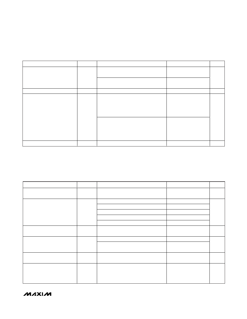
RECOMMENDED AC OPERATING CONDITIONS
PARAMETER
SYMBOL
CONDITIONS
MIN
TYP
MAX
UNITS
Typical Application Circuit with C1 = 8.2pF,
see Table 1 for details (Note 5)
2000
3000
RF Frequency Range
f
RF
Typical Application Circuit with C1 = 1.5pF,
see Table 1 for details (Note 5)
3000
3900
MHz
LO Frequency
f
LO
(Note 5)
2100
4000
MHz
Using Mini-Circuits TC4-1W-17 4:1
transformer as defined in the Typical
Application Circuit, IF matching
components affect the IF frequency range
(Note 5)
100
500
IF Frequency
f
IF
Using Mini-Circuits TC4-1W-7A 4:1
transformer as defined in the Typical
Application Circuit, IF matching
components affect the IF frequency range
(Note 5)
50
250
MHz
LO Drive
P
LO
-3
0
+3
dBm
PARAMETER
SYMBOL
CONDITIONS
MIN
TYP
MAX
UNITS
Small-Signal Conversion Gain
f
RF
= 2300MHz to 2900MHz, T
C
= +25°C
(Note 7)
7.9
8.7
9.2
dB
f
RF
= 2305MHz to 2360MHz
0.1
f
RF
= 2500MHz to 2570MHz
0.1
f
RF
= 2570MHz to 2620MHz
0.1
f
RF
= 2500MHz to 2690MHz
0.2
Gain Variation vs. Frequency
∆G
C
f
RF
= 2700MHz to 2900MHz
0.3
dB
Conversion Gain Temperature
Coefficient
TC
CG
T
C
= -40°C to +85°C
-0.012
dB/°C
No blockers present
9.8
12
Single Sideband Noise Figure
NF
SSB
f
R F
= 2600M H z, f
I F
= 300M H z, P
L O
= 0d Bm ,
V
C C
= + 5.0V , T
C
= + 25°C , no b l ocker s p r esent
9.8
10.5
dB
Noise Figure Temperature
Coefficient
TC
NF
f
RF
= 2300M H z to 2900M H z, si ng l e si d eb and ,
no b l ocker s p r esent, T
C
= - 40°C to + 85°C
0.018
dB/°C
Noise Figure Under Blocking
NF
B
+8dBm blocker tone applied to RF port,
f
RF
= 2600MHz, f
LO
= 2900MHz,
f
BLOCKER
= 2400MHz, P
LO
= 0dBm,
V
CC
= +5.0V, T
C
= +25°C (Note 8)
18
22
dB
5.0V SUPPLY AC ELECTRICAL CHARACTERISTICS—f
RF
= 2300MHz TO 2900MHz,
HIGH-SIDE LO INJECTION
(
Typical Application Circuit with tuning elements outlined in Table 1, V
CC
= 4.75V to 5.25V, RF and LO ports are driven from 50
Ω
sources, P
LO
= -3dBm to +3dBm, P
RF
= -5dBm, f
RF
= 2300MHz to 2900MHz, f
IF
= 300MHz, f
LO
= 2600MHz to 3200MHz, f
RF
< f
LO
,
T
C
= -40°C to +85°C. Typical values are for T
C
= +25°C, V
CC
= 5.0V, P
LO
= 0dBm, f
RF
= 2600MHz, f
LO
= 2900MHz, f
IF
= 300MHz.
All parameters are guaranteed by design and characterization, unless otherwise noted.) (Note 6)