Rainbow Electronics MAX7042 User Manual
Page 14
MAX7042
308MHz/315MHz/418MHz/433.92MHz
Low-Power, FSK Superheterodyne Receiver
14
______________________________________________________________________________________
Numerous configurations can be used to generate the
data-slicer threshold. For example, the circuit in Figure 3
shows a simple method using only one resistor and one
capacitor. This configuration averages the analog out-
put of the filter and sets the threshold to approximately
50% of that amplitude. With this configuration, the
threshold automatically adjusts as the analog signal
varies, minimizing the possibility for errors in the digital
data. The values of R and C affect how fast the thresh-
old tracks the analog amplitude. Be sure to keep the
corner frequency of the RC circuit much lower than the
lowest expected data rate.
With this configuration, a long string of zeros or ones
can cause the threshold to drift. This configuration
works best if a coding scheme, such as Manchester
coding, which has an equal number of zeros and ones,
is used.
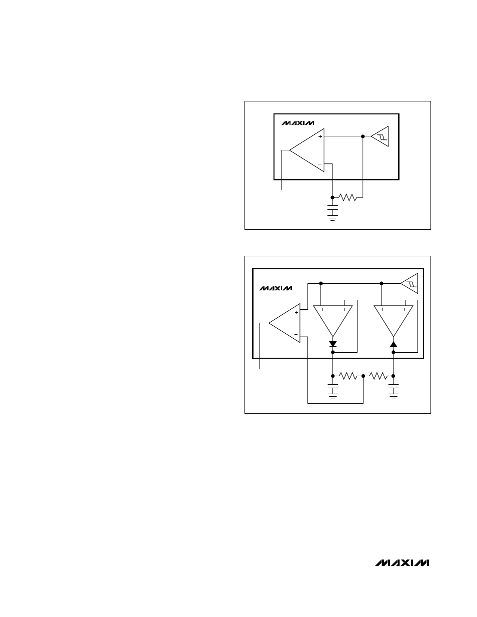
Figure 4 shows a configuration that uses the positive and
negative peak detectors to generate the threshold. This
configuration sets the threshold to the midpoint between
a high output and a low output of the data filter.
Peak Detectors
The maximum peak detector (PDMAX) and minimum
peak detector (PDMIN) outputs, in conjunction with a
resistor and capacitor connected to GND, create DC
output voltages proportional to the high- and low-peak
values of the data signal. The resistor provides a path
for the capacitor to discharge, allowing the peak detec-
tor to dynamically follow peak changes of the data-filter
output voltage.
The positive and negative peak detectors can be used
together to form a data-slicer threshold voltage at a
midvalue between the most positive and most negative
voltage levels of the data stream (see the Data Slicers
section and Figure 4). Set the RC time constant of the
peak-detector combining network to at least 5 times the
data period.
The MAX7042 peak detectors track the baseband filter
output voltage until all internal circuits are stable follow-
ing an enable pin low-to-high transition. This feature
allows for an extremely fast startup because the peak
detectors never “catch” a false level created by a startup
transient. The peak detectors exhibit a fast-attack/slow-
decay response.
Power-Supply Connections
The MAX7042 can be powered from a 2.4V to 3.6V
supply or a 4.5V to 5.5V supply. The device has an on-
chip linear regulator that reduces the 5V supply to 3V
needed to operate the chip.
To operate the MAX7042 from a 3V supply, connect
DV
DD
, AV
DD
, and HV
IN
to the 3V supply. When using a
5V supply, connect the supply to HV
IN
only. In both
cases, bypass DV
DD
and HV
IN
with a 0.01µF capacitor
and AV
DD
with a 0.1µF capacitor. Place all bypass
capacitors as close to the respective supply pin as
possible.
DATA
DS-
R
C
DS+
DATA
SLICER
MAX7042
Figure 3. Generating Data-Slicer Threshold
DATA
PDMAX
PDMIN
R
R
C
C
MAX7042
DATA
SLICER
PEAK
DET
PEAK
DET
Figure 4. Generating Data-Slicer Threshold Using the Peak
Detectors