Table 2. coefficients to calculate c, And c – Rainbow Electronics MAX7042 User Manual
Page 13
MAX7042
308MHz/315MHz/418MHz/433.92MHz
Low-Power, FSK Superheterodyne Receiver
______________________________________________________________________________________
13
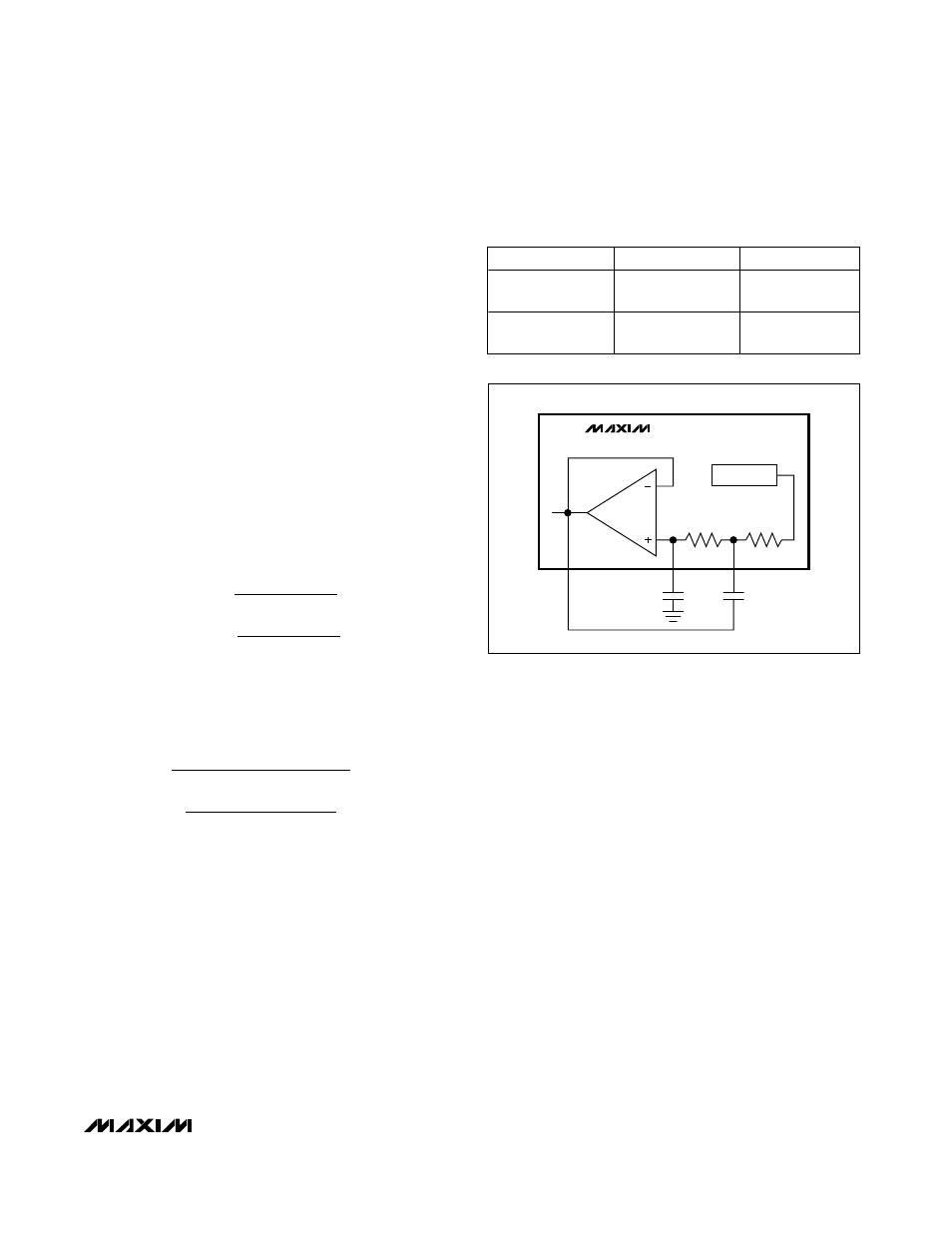
Data Filters
The data filter is implemented as a 2nd-order lowpass
Sallen-Key filter. The pole locations are set by the com-
bination of two on-chip resistors and two external
capacitors. Adjusting the value of the external capaci-
tors changes the corner frequency to optimize for dif-
ferent data rates. The corner frequency in kHz should
be to approximately the fastest expected data rate in
kbps for NRZ and twice the fastest expected data rate
in kbps for Manchester coding from the transmitter.
Keeping the corner frequency near the data rate
rejects any noise at higher frequencies, resulting in an
increase in receiver sensitivity.
The configuration shown in Figure 2 creates a Butterworth
or Bessel response. The Butterworth filter offers a very
flat amplitude response in the passband and a rolloff rate
of 40dB/decade for the two-pole filter. The Bessel filter
has a linear phase response, which works well for filter-
ing digital data. To calculate the value of the capacitors,
use the following equations along with the coefficients in
Table 2:
where f
C
is the desired 3dB corner frequency.
For example, choose a Butterworth filter response with
a 5kHz corner frequency:
Choosing standard capacitor values changes C
F1
to
470pF and C
F2
to 220pF. In the Typical Application
Circuit, C
F1
and C
F2
are named C4 and C3, respectively.
Data Slicer
The purpose of a data slicer is to take the analog output
of a data filter and convert it to a digital signal. This is
achieved by using a comparator and comparing the ana-
log input to a threshold voltage. The threshold voltage is
set by the voltage on the DS- pin, which is connected to
the negative input of the data-slicer comparator. The pos-
itive input of the data-slicer comparator is connected to
the output of the data filter internally.
C
k
kHz
pF
C
k
kHz
pF
F
F
1
2
1 000
1 414 100
3 14 5
450
1 414
4 100
3 14 5
225
.
( .
)(
)( .
)(
)
.
( )(
)( .
)(
)
=
≈
=
≈
Ω
Ω
C
b
a
k
f
C
a
k
f
F
C
F
C
1
2
100
4 100
(
)( )( )
(
)( )( )
=
=
Ω
Ω
π
π
Table 2. Coefficients to Calculate C
F1
and
C
F2
FILTER TYPE
a
b
Butterworth
(Q = 0.707)
1.414
1.000
Bessel
(Q = 0.577)
1.3617
0.618
FSK DEMOD
100k
Ω
DS+
OP+
C
F2
C
F1
DF
100k
Ω
MAX7042
Figure 2. Sallen-Key Lowpass Data Filter