Absolute maximum rat ings, Recommended dc operating conditions, Capacitance – Rainbow Electronics W982516CH User Manual
Page 5
W982516CH
Publication Release Date: Mar 2003
- 5 -
Revision A1
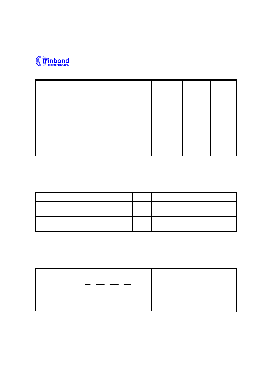
ABSOLUTE MAXIMUM RAT INGS
PARAMETER
SYMBOL
RATING
UNIT
NOTES
Input, Output Voltage
V
IN,
V
OUT
-0.3
−
V
CC
+
0.3
V
1
Supply Voltage
V
CC
, V
CCQ
-0.3
−
4.6
V
1
Operating Temperature(-6/-7/-75/75L)
T
OPR
0
−
70
°
C
1
Operating Temperature(75I)
T
OPR
-40
−
85
°
C
1
Storage Temperature
T
STG
-55
−
150
°
C
1
Soldering Temperature (10s)
T
SOLDER
260
°
C
1
Power Dissipation
P
D
1
W
1
Short Circuit Output Current
I
OUT
50
mA
1
Note 1: Exposure to conditions beyond those listed under Absolute Maximum Ratings may adversely affect the life and reliability
of the device.
RECOMMENDED DC OPERATING CONDITIONS
(Ta = 0 to 70°C for –6/-7/-75/75L, Ta=-40 to 85°C for 75I)
PARAMETER
SYMBOL
MIN.
TYP.
MAX.
UNIT
NOTES
Supply Voltage
V
CC
3.0
3.3
3.6
V
2
Supply Voltage (for I/O Buffer)
V
CCQ
3.0
3.3
3.6
V
2
Input High Voltage
V
IH
2.0
-
V
CC
+0.3
V
2
Input Low Voltage
V
IL
-0.3
-
0.8
V
2
Note 2: V
IH
(max) = V
CC
/ V
CC
Q+1.2V for pulse width < 5 nS
V
IL
( min) = V
SS
/ V
SS
Q-1.2V for pulse width < 5 nS
CAPACITANCE
(V
CC
= 3.3V, f = 1 MHz, T
A
= 25°C)
PARAMETER
SYMBOL
MIN.
MAX.
UNIT
Input Capacitance
(A0 to A12, BS0, BS1,
CS , RAS , CAS ,
WE , LDQM,
UDQM, CKE)
C
I
-
3.8
pf
Input Capacitance (CLK)
C
CLK
-
3.5
pf
Input/Output Capacitance
C
IO
-
6.5
pf
Note: These parameters are periodically sampled and not 100% tested.