Pin descriptions – Rainbow Electronics MAX5499 User Manual
Page 9
MAX5494–MAX5499
10-Bit, Dual, Nonvolatile, Linear-Taper
Digital Potentiometers
_______________________________________________________________________________________
9
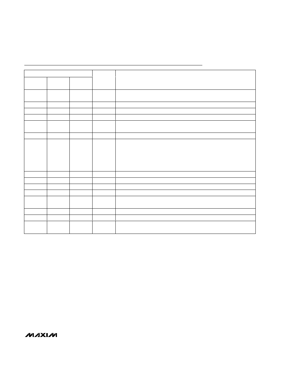
Pin Descriptions
PIN
MAX5494/
MAX5495
MAX5496/
MAX5497
MAX5498/
MAX5499
NAME
FUNCTION
1
1
1
CS
Active-Low Chip-Select Input. Drive CS low to enable the serial interface. Drive
CS high to disable the serial interface and put the device in standby mode.
2
2
2
W2
Wiper Terminal 2
3
3
3
L2
Low Terminal 2
4
—
—
H2
High Terminal 2
5
5
5
V
DD
Positive Power-Supply Input. 2.7V
≤ V
DD
≤ 5.25V. Bypass with a 0.1µF
capacitor from V
DD
to GND as close to the device as possible
6, 7,14,15
6, 7,14,15
6, 7,14,15
N.C.
No Connection. Not internally connected.
8
8
8
V
SS
Negative Power-Supply Input.
Single-supply operation: V
SS
= GND = 0.
Dual-supply operation: -2.5V
≤ V
SS
≤ -0.2V (V
SS
can vary as long as
(V
DD
- V
SS
)
≤ 5.25V).
Bypass with a 0.1µF capacitor from V
SS
to GND as close to the device
as possible.
9
—
9
H1
High Terminal 1
10
10
10
L1
Low Terminal 1
11
11
11
W1
Wiper Terminal 1
12
12
12
GND
Ground
13
13
13
DIN
Serial-Data Input. The data at DIN synchronously loads into the serial shift
register on each SCLK rising edge.
16
16
16
SCLK
Serial-Clock Input . SCLK clocks in the data when CS is low.
—
4, 9
4
D.N.C
Do Not Connect. Leave unconnected for proper operation.
EP
EP
EP
Exposed
Pad
Exposed Pad. Externally connect EP to V
SS
to provide a low thermal resistance
path from the IC junction to the PC board or leave unconnected.