Detailed description – Rainbow Electronics MAX5499 User Manual
Page 12
MAX5494–MAX5499
10-Bit, Dual, Nonvolatile, Linear-Taper
Digital Potentiometers
12
______________________________________________________________________________________
CODE (DECIMAL)
R
W_H_
(k
Ω
)
896
768
512 640
256 384
128
2
4
6
8
10
12
14
16
18
0
0
1024
50k
Ω SCALES BY A FACTOR OF FIVE
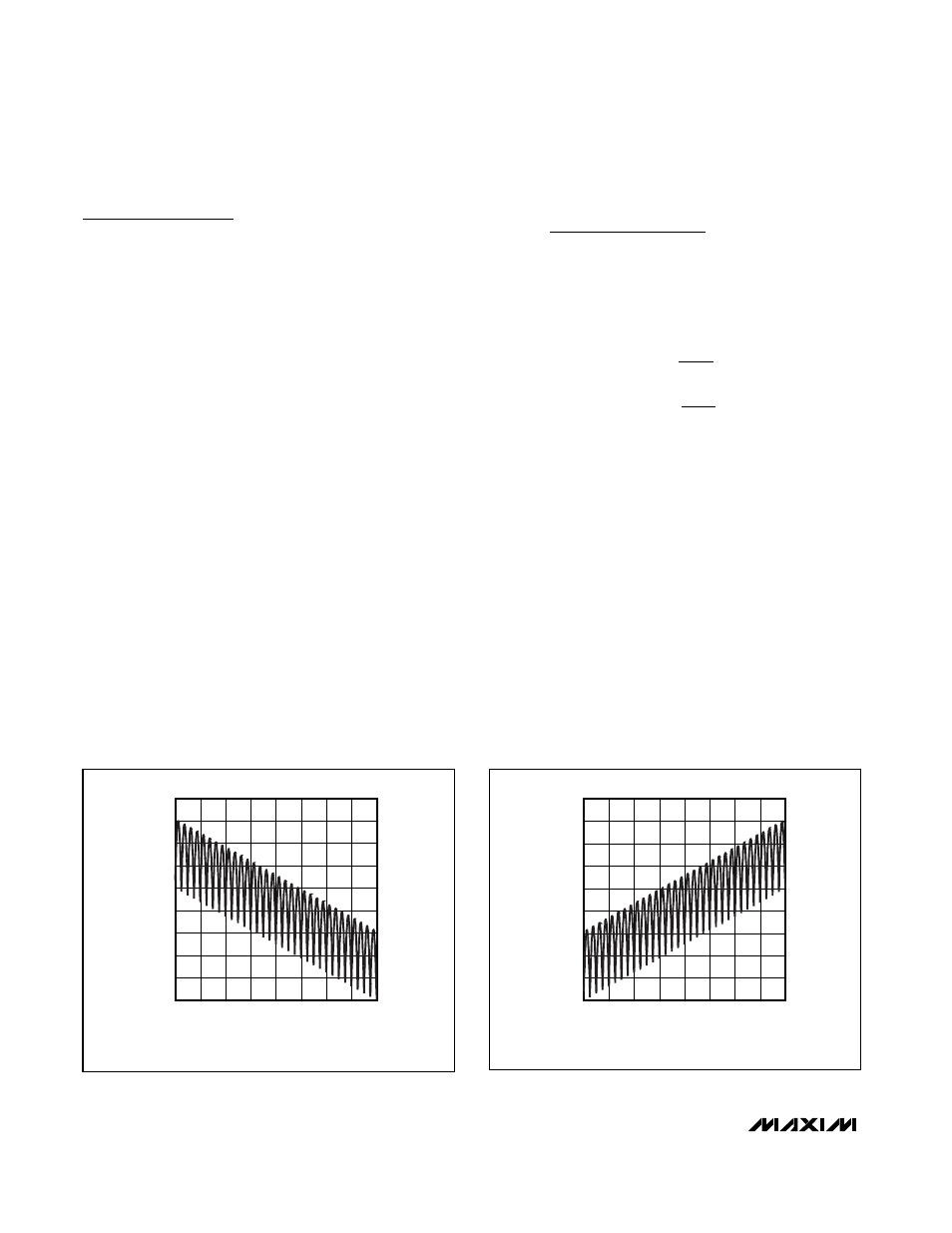
Figure 4. Resistance from W_ to H_ vs. Code (10k
Ω Voltage-
Divider)
CODE (DECIMAL)
R
W_L_
(k
Ω
)
896
768
512 640
256 384
128
2
4
6
8
10
12
14
16
18
0
0
1024
50k
Ω SCALES BY A FACTOR OF FIVE
Figure 5. Resistance from W_ to L_ vs. Code (10k
Ω Voltage-
Divider)
Detailed Description
The MAX5494–MAX5499 dual, nonvolatile, linear-taper,
programmable voltage-dividers and variable resistors
feature 1024 tap points (10-bit resolution) (see the
Functional Diagrams). These devices consist of multi-
ple strings of equal resistor segments with a wiper con-
tact that moves among the 1024 effective tap points by
a 3-wire SPI-compatible serial interface. The
MAX5494/MAX5496/MAX5498 provide a total 10k
Ω
end-to-end resistance, and the MAX5495/MAX5497/
MAX5499 feature a 50k
Ω end-to-end resistance. The
MAX5494/MAX5495/MAX5498/MAX5499 allow access
to the high, low, and wiper terminals for a standard volt-
age-divider configuration. Ensure that the terminal volt-
ages fall between V
SS
and V
DD
.
MAX5494/MAX5495/MAX5498/MAX5499
Programmable Voltage-Dividers
The MAX5494/MAX5495/MAX5498/MAX5499 program-
mable voltage-dividers provide a weighted average of
the voltage between the H_ and L_ inputs at the W_
output.
The MAX5494/MAX5495/MAX5498/MAX5499 program-
mable voltage-divider network provides up to 1024
division ratios between the H_ and L_ voltage. Ideally,
the V
L
voltage occurs at the wiper terminal when all
data bits are zeros and the V
H
voltage occurs at the
wiper terminal when all data bits are one (see the wiper
voltage equation). The step-size voltage (1 LSB) is
equal to the voltage applied across terminals H and L
divided by 2
10
. Calculate the wiper voltage V
W
as fol-
lows:
where D is the decimal equivalent of the 10 data bits
written (0 to 1023), V
HL
is the voltage difference between
the H_ and L_ terminals, and:
The MAX5494/MAX5498 provide a 10k
Ω end-to-end
resistance value, while the MAX5495/MAX5499 feature a
50k
Ω end-to-end resistance value. Note that the pro-
grammable voltage-divider is not intended to be used
as a variable resistor. Wiper current creates a nonlinear
voltage drop in series with the wiper. To ensure tempera-
ture drift remains within specifications, do not pull current
through the voltage-divider wiper. Connect the wiper to a
high-impedance node. Figures 4 and 5 show the behav-
ior of the programmable voltage-divider resistance from
W_ to H_ and W_ to L_, respectively. This does not apply
to the variable-resistor devices.
MAX5496–MAX5499 Variable Resistors
The MAX5496–MAX5499 provide a programmable resis-
tance from W_ to L_. The MAX5496/MAX5498 provide a
10k
Ω end-to-end resistance value, while the
MAX5497/MAX5499 feature a 50k
Ω end-to-end resis-
tance value. The programmable resolution of this
V
FSE
V
V
ZSE
V
FSE
HL
ZSE
HL
=
=
1024
1024
D
V
V
V
V
V
HL
FSE
ZSE
L
ZSE
−
+
(
)
+
+
|
|
|
|
|
|
1023