Timing characteristics – Rainbow Electronics MAX5499 User Manual
Page 5
MAX5494–MAX5499
10-Bit, Dual, Nonvolatile, Linear-Taper
Digital Potentiometers
_______________________________________________________________________________________
5
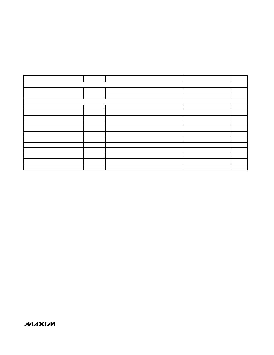
TIMING CHARACTERISTICS
(V
DD
= +2.7V to +5.25V, V
SS
= GND = 0, V
H_
= V
DD
, V
L_
= 0, T
A
= -40°C to +85°C, unless otherwise noted. Typical values are at
V
DD
= +5.0V, T
A
= +25°C.) (Note 1)
PARAMETER
SYMBOL
CONDITIONS
MIN
TYP
MAX
UNITS
ANALOG SECTION
MAX5494/MAX5498
5
Wiper Settling Time (Note 6)
t
S
MAX5495/MAX5499
22
µs
SPI-COMPATIBLE SERIAL INTERFACE (Figure 6)
SCLK Frequency
f
SCLK
7
MHz
SCLK Clock Period
t
CP
140
ns
SCLK Pulse-Width High
t
CH
60
ns
SCLK Pulse-Width Low
t
CL
60
ns
CS Fall to SCLK Rise Setup
t
CSS
60
ns
SCLK Rise to CS Rise Hold
t
CSH
0
ns
DIN to SCLK Setup
t
DS
40
ns
DIN Hold After SCLK
t
DH
0
ns
SCLK Rise to CS Fall Delay
t
CS0
15
ns
CS Rise to SCLK Rise Hold
t
CS1
60
ns
CS Pulse-Width High
t
CSW
150
ns
Write NV Register Busy Time
t
BUSY
12
ms
Note 1: 100% production tested at T
A
= +25°C and T
A
= +85°C. Guaranteed by design to T
A
= -40°C.
Note 2: The DNL and INL are measured for the voltage-divider with H_ = V
DD
and L_ = V
SS
. The wiper terminal (W_) is unloaded
and measured with a high-input-impedance voltmeter.
Note 3: The DNL and INL are measured with L_ = V
SS
= 0. For V
DD
= 5V, the wiper terminal is driven with a current source of I
W
=
80µA for the 50k
Ω device and I
W
= 400µA for the 10k
Ω device. For V
DD
= 3V, the wiper terminal is driven with a current
source of I
W
= 40µA for the 50k
Ω device and I
W
= 200µA for the 10k
Ω device.
Note 4: The wiper resistance is measured using the source currents given in Note 3.
Note 5: The device draws higher supply current when the digital inputs are driven with voltages between (V
DD
- 0.5V) and (GND +
0.5V). See the Supply Current vs. Digital Input Voltage graph in the Typical Operating Characteristics.
Note 6: Wiper settling test condition uses the voltage-divider with a 10pF load on W_. Transition code from 0 to 495 and measure
the time from CS going high to the wiper voltage settling to within 0.5% of its final value.