Message format for reading – Rainbow Electronics MAX6959 User Manual
Page 8
MAX6958/MAX6959
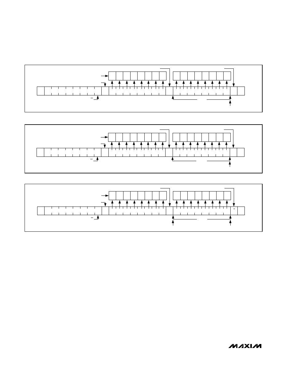
Bytes received after the command byte are data bytes.
The first data byte goes into the internal register of the
MAX6958/MAX6959 as selected by the command byte
(Figure 7).
The address pointer in the MAX6958/MAX6959 autoin-
crements after each data byte. If multiple data bytes
are transmitted before a STOP condition is detected,
these bytes are stored in subsequent MAX6958/
MAX6959 internal registers (Figure 8), unless the
address pointer has reached address 01111111. The
address pointer does not autoincrement once address
01111111 has been reached (Table 3).
Message Format for Reading
The MAX6958/MAX6959 are read using the internally
stored command byte as an address pointer the same
way the stored command byte is used as an address
pointer for a write. The pointer autoincrements after
each data byte read using the same rules as for a write
(Table 3). A read is initiated by first configuring the
MAX6958/MAX6959s’ command byte with a write com-
mand (Figure 6). The master can now read n consecu-
tive bytes from the MAX6958/MAX6959. The master
acknowledges receipt of each read byte during the
acknowledge clock pulse. The master must acknowl-
edge all consecutive bytes received except the last
byte. The final read byte must be followed by a not
acknowledge from the master and then a stop condi-
tion (Figure 9). The first data byte is read from the reg-
ister addressed by the initialized command byte
(Figure 8). Reset the address pointer when performing
read-after-write verification because the stored byte
address is autoincremented after the write. The
address pointer does not autoincrement if it points to
register 01111111 (Table 3).
Table 4 is the register address map.
2-Wire Interfaced, 3V to 5.5V, 4-Digit,
9-Segment LED Display Drivers with Keyscan
8
_______________________________________________________________________________________
A
0
SLAVE ADDRESS
COMMAND BYTE
DATA BYTE
ACKNOWLEDGE FROM
MAX6958/MAX6959
R/W
1 BYTE
AUTOINCREMENT MEMORY WORD ADDRESS
ACKNOWLEDGE FROM MAX6958/MAX6959
ACKNOWLEDGE FROM MAX6958/MAX6959
D15
D14 D13 D12 D11 D10
D9
D8
D1
D0
D3
D2
D5
D4
D7
D6
HOW CONTROL BYTE AND DATA BYTE MAP INTO
MAX6958/MAX6959s' REGISTERS
S
A
A
P
Figure 7. Command and Single Data Byte Received
A
0
SLAVE ADDRESS
COMMAND BYTE
DATA BYTE
ACKNOWLEDGE FROM
MAX6958/MAX6959
R/W
n BYTES
AUTOINCREMENT MEMORY WORD ADDRESS
ACKNOWLEDGE FROM MAX6958/MAX6959
ACKNOWLEDGE FROM MAX6958/MAX6959
D15
D14 D13 D12 D11 D10
D9
D8
D1
D0
D3
D2
D5
D4
D7
D6
HOW CONTROL BYTE AND DATA BYTE MAP INTO
MAX6958/MAX6959s' REGISTERS
S
A
A
P
Figure 8. n Data Bytes Received
1
SLAVE ADDRESS
FIRST DATA BYTE
DATA BYTE
ACKNOWLEDGE FROM MAX6958/MAX6959
R/W
n BYTES
AUTOINCREMENT MEMORY WORD ADDRESS
ACKNOWLEDGE FROM THE MASTER
NOT ACKNOWLEDGE FROM MASTER
D15
D14 D13 D12 D11 D10
D9
D8
D1
D0
D3
D2
D5
D4
D7
D6
HOW THE MAX6958/MAX6959 SENDS DATA
TO THE MASTER
S
A
A
P
AUTOINCREMENT MEMORY WORD ADDRESS
A
Figure 9. Reading n Data Bytes from the MAX6958/MAX6959