Chip information, Ordering information (continued), Functional diagram – Rainbow Electronics MAX6959 User Manual
Page 17
Computing Power Dissipation
Determine the MAX6958/MAX6959 upper-limit power
dissipation (P
D
) with the following equation:
P
D
= (V+
✕
I+) + (V+ - V
LED
) (DUTY
✕
I
SEG
✕
N)
where:
V+ = supply voltage
I+ = operating supply current
DUTY = duty cycle set by intensity register
N = number of segments driven (worst case is nine)
V
LED
= LED forward voltage at I
SEG
I
SEG
= peak segment current
P
D
= power dissipation, in mW if currents are in mA
Dissipation example:
I
SEG
= 23mA, N = 9, DUTY = 63/64, V
LED
= 2.2V,
V+ = 5.25V
P
D
= 5.25V (5.9mA) + (5.25V - 2.2V)
(63/64
✕
23mA
✕
9) = 0.652W
For a 16-pin DIP package (T
JA
= 1/0.0105 = +95.2°C/W
from Absolute Maximum Ratings), the maximum
allowed ambient temperature T
A
is given by:
T
J(MAX)
= T
A
+ (P
D
✕
T
JA
) = +150°C
= T
A
+ (0.652
✕
95.2°C/W)
Therefore, T
A
= +87.9°C.
Power Supplies
The MAX6958/MAX6959 operate from a single 3V to
5.5V power supply. Bypass V+ with a 0.1µF capacitor
to GND, as close to the device as possible. Bypass V+
with an additional 10µF capacitor if the MAX6958/
MAX6959 are not close to the board input’s bulk
decoupling capacitor.
Chip Information
TRANSISTOR COUNT: 17,340
PROCESS: CMOS
MAX6958/MAX6959
2-Wire Interfaced, 3V to 5.5V, 4-Digit,
9-Segment LED Display Drivers with Keyscan
______________________________________________________________________________________
17
Ordering Information (continued)
PART
TEMP
RANGE
SLAVE
ADDRESS
PIN-
PACKAGE
MAX6958BAEE
-40
°C to +125°C
0111001
16 QSOP
MAX6958BAPE
-40
°C to +125°C
0111001
16 DIP
MAX6959AAEE
-40
°C to +125°C
0111000
16 QSOP
MAX6959AAPE
-40
°C to +125°C
0111000
16 DIP
MAX6959BAEE
-40
°C to +125°C
0111001
16 QSOP
MAX6959BAPE
-40
°C to +125°C
0111001
16 DIP
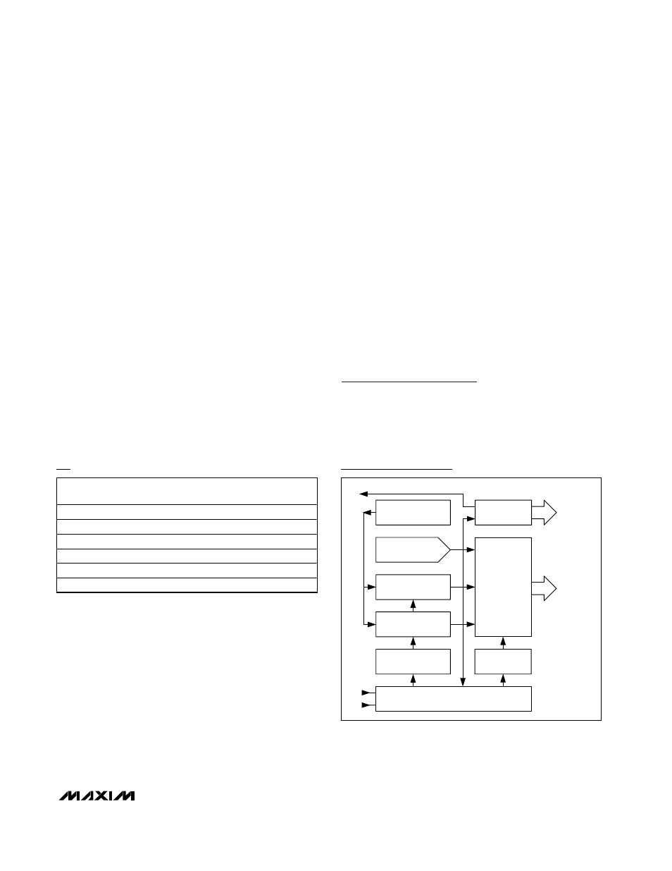
CONFIGURATION
REGISTERS
DISPLAY RAM
AND HEX ROM
SCL
SDA
2-WIRE SERIAL INTERFACE
MULTIPLEX
LOGIC
4 LED DIGITS
KEYSCAN AND
LED
DRIVER
CURRENT
REFERENCE
MULTIPLEX
OSCILLATOR
PWM INTENSITY
CONTROL
PORT CONTROL
PORTS AND
KEYSCAN
IRQ
Functional Diagram