Table 7. decode-mode register examples – Rainbow Electronics MAX6959 User Manual
Page 10
MAX6958/MAX6959
The digit registers and segments register use 1 bit to
set the state of one segment. Each bit is high to turn a
segment on, or low to turn it off (Table 6).
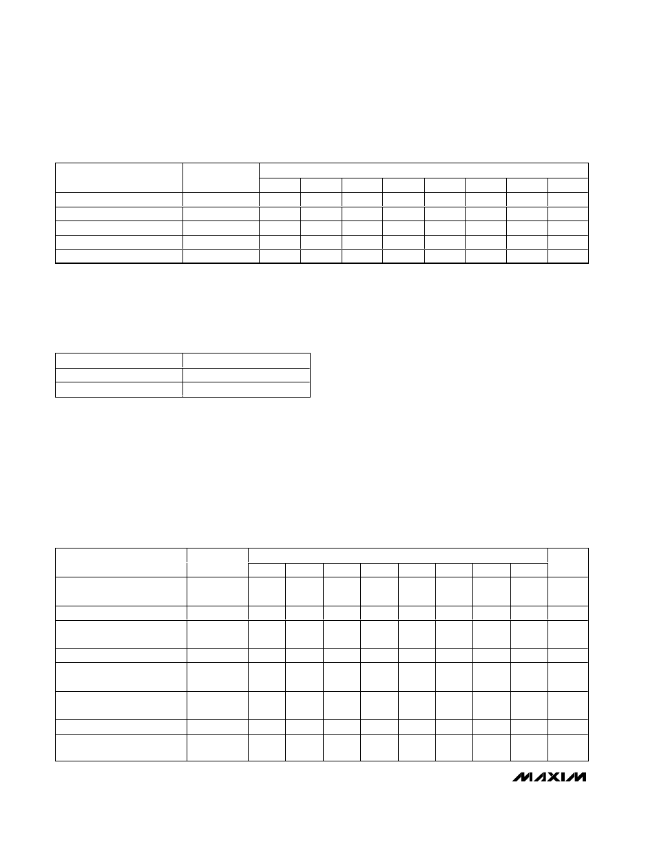
Decode-Mode Register
The decode-mode register sets hexadecimal code
(0–9, A–F) or no-decode operation for each digit. Each
bit in the register corresponds to one digit. Logic high
selects hexadecimal decoding while logic low bypass-
es the decoder. Digits can be set for decode or no
decode in any combination. Bit assignment and exam-
ples of the decode mode control register format are
shown in Table 7.
In hexadecimal code-decode mode, the decoder looks
only at the lower nibble of the data in the digit register
(D3–D0), disregarding bits D7–D4. Table 7 lists the hexa-
decimal code font. When no decode is selected, data
bits D7–D0 correspond to the segment lines of the
MAX6958/MAX6959. Table 8 shows the one-to-one pair-
ing of each data bit to the appropriate segment line.
Initial Power-Up
On initial power-up, all control registers are reset, the
display is blanked, and the MAX6958/MAX6959 enter
shutdown mode (Table 9). At power-up, the MAX6958/
MAX6959 are initially set to scan four digits, do not
decode data in the digit registers or scan key switches
(MAX6959 only), and the intensity register is set to a
low value (4/64 intensity).
2-Wire Interfaced, 3V to 5.5V, 4-Digit,
9-Segment LED Display Drivers with Keyscan
10
______________________________________________________________________________________
REGISTER DATA
DIGIT/SEGMENT REGISTER
ADDRESS
CODE (HEX)
D7
D6
D5
D4
D3
D2
D1
D0
Digit 0
0x20
X
SEG a
SEG b
SEG c
SEG d
SEG e
SEG f
SEG g
Digit 1
0x21
X
SEG a
SEG b
SEG c
SEG d
SEG e
SEG f
SEG g
Digit 2
0x22
X
SEG a
SEG b
SEG c
SEG d
SEG e
SEG f
SEG g
Digit 3
0x23
X
SEG a
SEG b
SEG c
SEG d
SEG e
SEG f
SEG g
Segments
0x24
SEG 7
SEG 6
SEG 5
SEG 4
SEG 3
SEG 2
SEG 1
SEG 0
Table 5. No-Decode Mode Data Bits and Corresponding Segment Lines
REGISTER BIT
SEGMENT BEHAVIOR
0
Segment off
1
Segment on
Table 6. No-Decode Mode Data Bits and
Corresponding Segment Lines
REGISTER DATA
DECODE MODE
ADDRESS
CODE (HEX)
D7
D6
D5
D4
D3
D2
D1
D0
HEX
CODE
Bit assignment for each digit
0x01
X
X
X
X
Digit 3
Digit 2
Digit 1
Digit 0
—
No decode for digits 3–0
0x01
X
X
X
X
0
0
0
0
0xX0
Hexadecimal decode for digit
0; no decode for digits 3–1
0x01
X
X
X
X
0
0
0
1
0xX1
—
—
—
—
—
—
—
—
—
—
—
Hexadecimal decode for digits
2–0; no decode for digit 3
0x01
X
X
X
X
0
1
1
1
0xX7
Hexadecimal decode for digit
3; no decode for digits 2–0
0x01
X
X
X
X
1
0
0
0
0xX8
—
—
—
—
—
—
—
—
—
—
—
Hexadecimal decode for digits
3–0
0x01
X
X
X
X
1
1
1
1
0xXF
Table 7. Decode-Mode Register Examples