Applications information, Table 17. key debounced register format, Table 18. key pressed register format – Rainbow Electronics MAX6959 User Manual
Page 16: Table 19. display test register
MAX6958/MAX6959
Key Debounced Register (MAX6959 Only)
The key debounced register shows which keys have
been detected as debounced by the keyscanning cir-
cuit (Table 17). Each bit in the register corresponds to
one key switch. The bit is set to 1 if the switch has been
correctly debounced since the last key debounced reg-
ister read operation.
Reading the key debounced register clears the register
(after the data has been read) so that future key presses
can be identified. If the key debounced register is not
read, the keyscan data accumulates. There is no FIFO
register in the MAX6959. Key-press order, or whether a
key has been pressed more than once, cannot be
determined unless the key debounced register is read
after each interrupt and before completion of the next
keyscan cycle.
Reading the key debounced register clears the IRQ
output. If a key is pressed and held down, the key is
reported as debounced (and an IRQ is issued) only
once. The key must be detected as released by the
keyscanning circuit before it is debounced again.
The key debounced register is read only. A write to
address 0x08 is ignored.
Key Pressed Register (MAX6959 Only)
The key pressed register shows which keys have been
detected as pressed by the keyscanning circuit during
the last test. Each bit in the register corresponds to one
key switch. The bit is set if the switch has been detect-
ed as pressed by the keyscanning circuit during the
last test. The bit is cleared if the switch has not been
detected as pressed by the keyscanning circuit during
the last test. Reading the key pressed register does not
clear either the key pressed register, or the key
debounced register, and does not clear the IRQ output.
The key pressed register is read only. A write to
address 0x0C is ignored.
Display Test Register
The display test register operates in two modes: normal
and display test (Table 19). Display test mode turns on
all LEDs by overriding, but not altering, all control and
digit registers (including the shutdown register) except
for the port configuration register. The duty cycle while
in display test mode is 28/64.
Applications Information
Driving Bicolor LEDs
Bicolor digits combine a red and a green die for each
display element, so that the element displays red or
green (or orange), depending on which die (or both) is
lit. The MAX6958/MAX6959 treat a bicolor digit as two
monocolor digits.
Low-Voltage Operation
The MAX6958/MAX6959 are guaranteed to drive a 23mA
segment current into 2.4V (or lower) LEDs when operat-
ed from a supply voltage of 4.5V to 5.5V. Operating the
MAX6958/MAX6959 from a supply voltage lower than
4.5V reduces the LED drive current. The drivers drive at
least 15.5mA segment current into 2V (or lower) LEDs
when operated from a 3V supply voltage.
2-Wire Interfaced, 3V to 5.5V, 4-Digit,
9-Segment LED Display Drivers with Keyscan
16
______________________________________________________________________________________
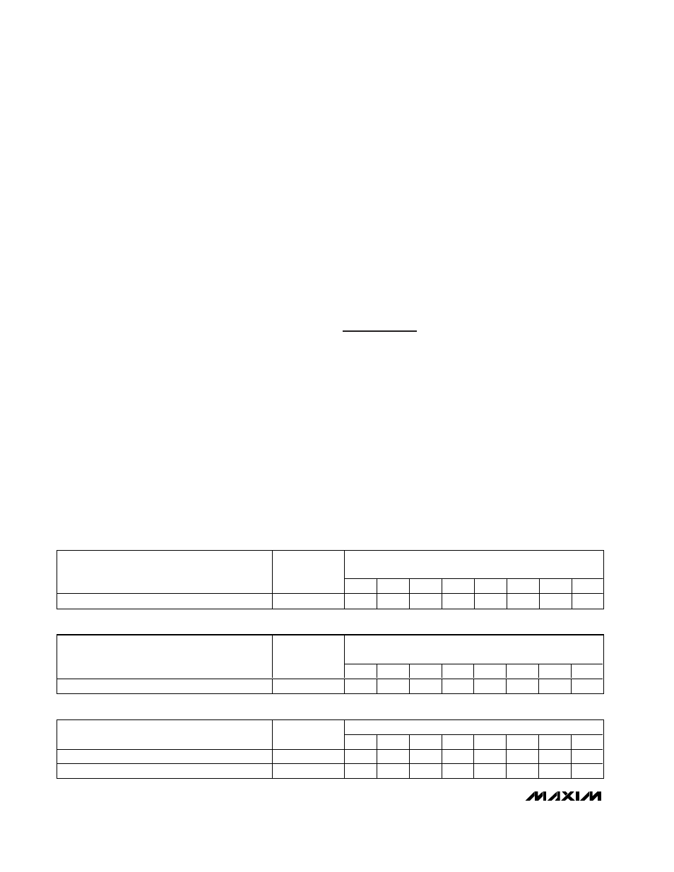
REGISTER DATA
WITH APPROPRIATE SWITCH NAMED BELOW
KEY DEBOUNCED REGISTER
ADDRESS
CODE (HEX)
D7
D6
D5
D4
D3
D2
D1
D0
Key debounced register
0x08
Key7
Key6
Key5
Key4
Key3
Key2
Key1
Key0
Table 17. Key Debounced Register Format
REGISTER DATA
WITH APPROPRIATE SWITCH NAMED BELOW
KEY PRESSED REGISTER
ADDRESS
CODE (HEX)
D7
D6
D5
D4
D3
D2
D1
D0
Key pressed register
0x0C
Key7
Key6
Key5
Key4
Key3
Key2
Key1
Key0
Table 18. Key Pressed Register Format
REGISTER DATA
MODE
ADDRESS
CODE (HEX)
D7
D6
D5
D4
D3
D2
D1
D0
Normal operation
0x07
X
X
X
X
X
X
X
0
Display test mode
0x07
X
X
X
X
X
X
X
1
Table 19. Display Test Register