Pin description, Typical operating characteristics (continued) – Rainbow Electronics MAX7394 User Manual
Page 5
MAX7393/MAX7394
Precision Silicon Oscillators with
Enable or Autoenable
_______________________________________________________________________________________
5
Pin Description
PIN
MAX7393
MAX7394
NAME
FUNCTION
1
1
V
CC
Positive Supply Voltage Input. Bypass V
CC
to GND with 0.1µF capacitors placed as close to
the device as possible. Connect V
CC
to V
CC2
.
2
2
GND
Ground
3
3
I.C.
Internally Connected. Connect I.C. to GND. Do not connect I.C. to any other input or output.
Do not leave I.C. unconnected.
4
—
CLKIN
Clock Input. Connect CLKIN to a returned clock signal source (see the Autoenable (CLKIN,
MAX7393) section).
5
5
CLOCK
Clock Output. CLOCK is a rail-to-rail, push-pull output.
6
6
V
CC2
Positive Supply Voltage Input for Output Driver. Bypass V
CC2
to GND with a 0.1µF capacitor
placed as close to the device as possible. Connect V
CC2
to V
CC
.
—
4
ENABLE
Enable Input. Drive ENABLE low to place the MAX7394 in shutdown mode. Drive ENABLE
high for normal operation.
—
—
EP
Exposed Paddle, TDFN Version Only. Connect EP to ground. Do not connect EP to any other
input or output.
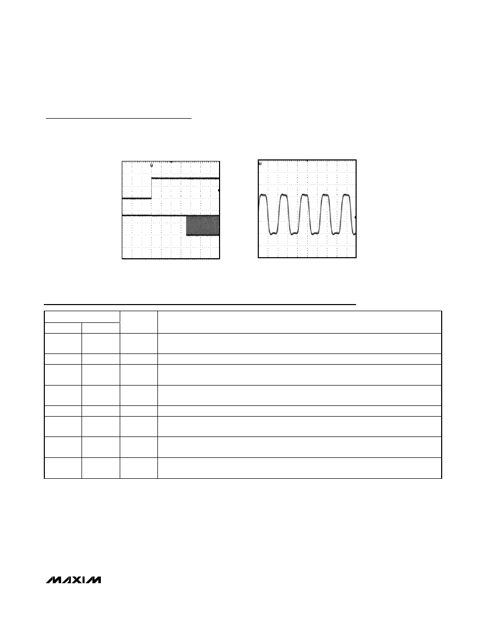
MAX7394 SETTLING TIME FROM START
MAX7393 toc09
CLOCK
2V/div
ENABLE
2V/div
400
µs/div
CLOCK OUTPUT WAVEFORM
WITH C
L
= 10pF
MAX7393 toc10
CLOCK
1V/div
10ns/div
Typical Operating Characteristics (continued)
(V
CC
= V
CC2
= 3.3V, T
A
= +25°C, MAX7394, 48MHz output, unless otherwise noted.)