Max5406 audio processor with pushbutton interface, Electrical characteristics (continued) – Rainbow Electronics MAX5406 User Manual
Page 4
MAX5406
Audio Processor with Pushbutton Interface
4
_______________________________________________________________________________________
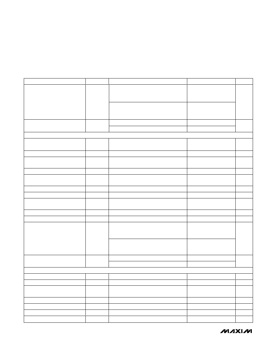
PARAMETER
SYMBOL
CONDITIONS
MIN
TYP
MAX
UNITS
f
BW
= 20Hz to 20kHz, V
IN
= V
BIAS
,
mute on, noise measured at LOUT and
ROUT (Notes 2, 4, 5)
3.5
9.5
Output Noise
e
n
f
BW
= 20Hz to 20kHz, V
IN
= V
BIAS
, mute
off, volume = 0dB, noise measured at
LOUT and ROUT (Notes 2, 4, 5)
25
35
µV
RMS
100mV
P-P
at 217Hz on V
DD
-70
Power-Supply Rejection Ratio
PSRR
100mV
P-P
at 1kHz on V
DD
-65
dB
SUBWOOFER OUTPUT
Gain
(V
L1_H
- V
L1_L
) to (V
SUBOUT
- V
BIAS
),
volume = 0dB (Note 2)
-6
dB
Highpass Filter Cutoff Frequency
Volume = 0dB
15
Hz
Internal Highpass Cutoff
Resistance
R
_S
Figure 12
13.8
k
Ω
Lowpass Filter Cutoff Frequency
Volume = 0dB
100
Hz
Internal Lowpass Cutoff
Resistance
R
SUB
Figure 12
10.6
k
Ω
Maximum Load Capacitance
C
SUBLOAD
100
pF
Output-Voltage Swing
V
SUBOUTP-P
R
L
= 10k
Ω, V
DD
= +2.7V, V
SS
= -2.7V
-2.3
+2.3
V
Output Offset Voltage
V
SUBOOS
V
DD
= +2.7V, V
SS
= -2.7V, volume = 0dB,
R
L
= 10k
Ω
-15
0
+15
mV
Short-Circuit Output Current
I
SUBSC
Shorted to V
SS
12
mA
Output Resistance
R
SUBOUT
I
LOAD
= 100µA to 500µA
10
Ω
f
BW
= 20Hz to 20kHz, V
IN
= V
BIAS
,
mute on, noise measured at SUBOUT
(Notes 2, 4, 5)
9
11
Output Noise
e
n
f
BW
= 20Hz to 20kHz, V
IN
= V
BIAS
,
volume = 0dB, mute off, noise measured at
SUBOUT (Notes 2, 4, 5)
25
35
µV
RMS
100mV
P-P
at 217Hz on V
DD
-70
Power-Supply Rejection Ratio
PSRR
100mV
P-P
at 1kHz on V
DD
-65
dB
PUSHBUTTON CONTACT INPUTS (
MUTE, AMB, VOLUP, VOLDN, BALL, BALR, BASSUP, BASSDN, TREBUP, TREBDN)
Internal Pullup Resistor
R
PU
50
k
Ω
Single-Pulse Input Low Time
t
LPW
Figures 2a, 11a, 11b
30
ms
Repetitive Input Pulse Separation
Time
t
HPW
Figure 2b, 11a, 11b
40
ms
First Autoincrement Point
t
A1
Figure 3
1
s
First Autoincrement Rate
f
A1
Figure 3
4
Hz
Second Autoincrement Point
t
A2
Figure 3
4
s
Second Autoincrement Rate
f
A2
Figure 3
16
Hz
ELECTRICAL CHARACTERISTICS (continued)
(V
DD
= V
LOGIC
= +5.0V, V
SS
= 0, V
BIAS
= V
CMSNS
= V
DD
/ 2, DGND = 0, ambience disabled, V
AMBLI
= V
AMBRI
= V
BIAS,
V
R1_L
=
V
L1_L
= V
R2_L
= V
L2_L
= external V
BIAS
, C
CSUB
= 0.15µF, C
CLS
= C
CRS
= 1µF, C
CBL
= C
CBR
= 3.3nF, C
CTL
= C
CTR
= 4.7nF, C
BIAS
=
0.1µF, C
CBIAS
= 50µF (see the Typical Application Circuit), T
A
= T
MIN
to T
MAX
unless otherwise specified. Typical values are at T
A
=
+25°C). (Note1)