Max5406 audio processor with pushbutton interface, Package information (continued), Boblet – Rainbow Electronics MAX5406 User Manual
Page 26
MAX5406
Audio Processor with Pushbutton Interface
Boblet
Maxim cannot assume responsibility for use of any circuitry other than circuitry entirely embodied in a Maxim product. No circuit patent licenses are
implied. Maxim reserves the right to change the circuitry and specifications without notice at any time.
26
____________________Maxim Integrated Products, 120 San Gabriel Drive, Sunnyvale, CA 94086 408-737-7600
© 2006 Maxim Integrated Products
Printed USA
is a registered trademark of Maxim Integrated Products, Inc.
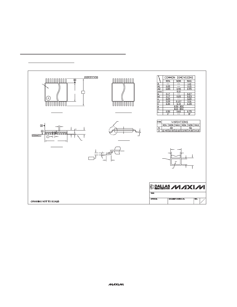
Package Information (continued)
(The package drawing(s) in this data sheet may not reflect the most current specifications. For the latest package outline information,
go to www.maxim-ic.com/packages.)
48L TSSOP.EPS
NOTES:
1. DIMENSIONS D & E ARE REFERENCE DATUMS AND DO NOT INCLUDE MOLD FLASH.
2. MOLD FLASH OR PROTRUSIONS NOT TO EXCEED 0.15MM ON D SIDE, AND 0.25MM ON E SIDE.
3. CONTROLLING DIMENSION: MILLIMETERS.
4. THIS PART IS COMPLIANT WITH JEDEC SPECIFICATION MO-153, VARIATIONS, ED (48L), EE (56L).
5. "N" REFERS TO NUMBER OF LEADS.
6. THE LEAD TIPS MUST LIE WITHIN A SPECIFIED ZONE. THIS TOLERANCE ZONE IS DEFINED BY TWO PARALLEL
PLANES. ONE PLANE IS THE SEATING PLANE, DATUM (-C-), THE OTHER PLANE IS AT THE SPECIFIED DISTANCE
FROM (-C-) IN THE DIRECTION INDICATED.
7. MARKING IS FOR PACKAGE ORIENTATION REFERENCE ONLY.
8. NUMBER OF LEADS SHOWN ARE FOR REFERENCE ONLY.
SECTION C-C
DETAIL A
N
SIDE VIEW
TOP VIEW
CL
1
H
E
e
D
b
A
A2
A1
BOTTOM VIEW
c
0.25
(
)
b1
b
c1
BASE METAL
c
END VIEW
SEATING
PLANE
SEE DETAIL A
PARTING
LINE
WITH PLATING
L
PACKAGE OUTLINE,
21-0155
1
1
C
48 & 56L TSSOP, 6.1mm BODY
AAA
2 3
A
MARKING