Dte/dce mode applications – Rainbow Electronics MAX13175E User Manual
Page 31
MAX13171E/MAX13173E/MAX13175E
Multiprotocol, Pin-Selectable
Data Interface Chipset
______________________________________________________________________________________
31
DTE/DCE Mode Applications
The MAX13171E/MAX13173E can be hardwired for
either DTE or DCE mode in one of two ways: a dedicat-
ed DTE or DCE port with an appropriate gender con-
nector, or a port with a connector that can be configured
for DTE or DCE operation by rerouting the signals to the
MAX13171E and MAX13173E, using a dedicated DTE
cable or dedicated DCE cable. The interface mode is
selected by logic outputs from the controller or from
jumpers to either V
L
or GND on the mode select inputs.
A dedicated DCE port using a DB-25 female connector
is shown in Figure 28. Figure 29 illustrates a dedicated
DTE port using a DB-25 male connector.
Figure 27 shows an application circuit with one com-
mon DB-25 connector that can be configured for either
DTE or DCE mode. The configuration requires separate
cables for proper signal routing in DTE or DCE opera-
tion. Figure 27 illustrates a DCE or DTE controller-selec-
table interface. The DCE/DTE and INVERT inputs switch
the port’s mode of operation (Tables 1, 2).
50Ω
50Ω
125Ω
50Ω
50Ω
125Ω
A′
B′
C′
A
B
C
GND
GND
GENERATOR
BALANCED
INTERCONNECTING
CABLE
CABLE
TERMINATION
RECEIVER
LOAD
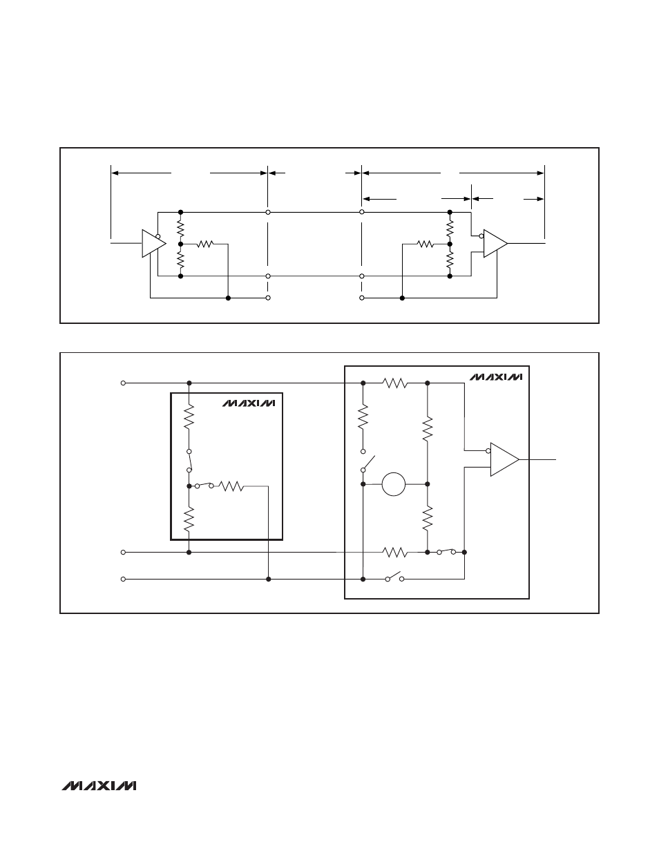
Figure 25. Typical V.35 Interface
R6
11kΩ
R8
5kΩ
R3
127Ω
R2
52Ω
R1
52Ω
A′
B′
C′
A
B
GND
R5
55kΩ
1.4V
R7
11kΩ
R4
55kΩ
MAX13175E
MAX13171E
S3
S1
RECEIVER
S2
S1
+
-
S2
Figure 26. V.35 Termination and Internal Resistance Networks