Rainbow Electronics MAX13175E User Manual
Page 18
MAX13171E/MAX13173E/MAX13175E
Multiprotocol, Pin-Selectable
Data Interface Chipset
18
______________________________________________________________________________________
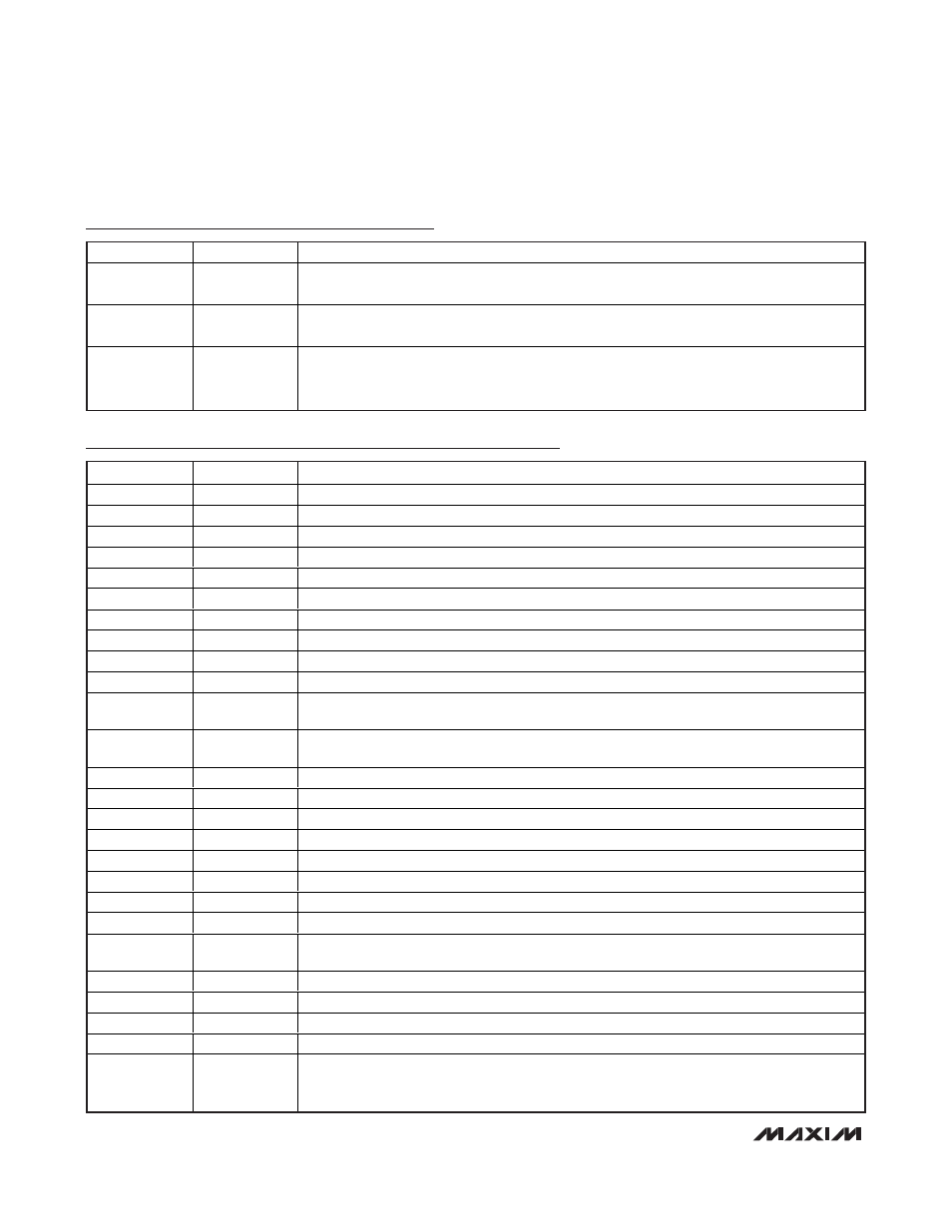
MAX13173E Pin Description (continued)
PIN
NAME
FUNCTION
37
C1+
V
DD
Charge-Pump Flying-Capacitor Positive Terminal. Connect a 1µF ceramic capacitor
between C1+ and C1-.
38
V
DD
Charge-Pump Positive-Supply Output. Connect a 4.7µF ceramic capacitor from V
DD
to ground
as close as possible to the device.
—
EP
Exposed Pad. Internally connected to V
EE
. Connect to a large V
EE
plane to maximize thermal
performance, not intended as an electrical connection point. Does not share the same plane as
the MAX13171E.
MAX13175E Pin Description
PIN
NAME
FUNCTION
1, 38
R1B
Load 1, Node B
2, 3
R1A
Load 1, Node A
4, 5
R2A
Load 2, Node A
6, 7
R2B
Lode 2, Node B
8
R2C
Lode 2, Center Tap
9, 10
R3A
Load 3, Node A
11, 12
R3B
Lode 3, Node B
13, 18
GND
Ground
14
R3C
Lode 3, Center Tap
15
V
L
Logic-Supply Reference Input. V
L
determines the voltage level of the logic interface.
16
V
EE
Negative Supply Voltage. Bypass V
EE
to GND with a 0.1µF capacitor. Connect to V
EE
from the
MAX13173E.
17
V
DD
Positive Supply Voltage. Bypass V
DD
to GND with a 0.1µF capacitor. Connect to V
DD
from the
MAX13173E.
19
V
CC
Supply Voltage. Bypass V
CC
to GND with a 0.1µF capacitor as close as possible to the device.
20, 21
R4B
Load 4, Node B
22, 23
R4A
Load 4, Node A
24, 25
R5B
Load 5, Node B
26, 27
R5A
Load 5, Node A
28, 29
R6A
Load 6, Node A
30, 31
R6B
Load 6, Node B
32
DCE/DTE
DCE/DTE Mode-Select Input
33
LATCH
Latch Signal Input. When LATCH is low, the input latches are transparent. When LATCH is high,
the data at the mode-select inputs are latched.
34
M2
Mode-Select Input 2
35
M1
Mode-Select Input 1
36
M0
Mode-Select Input 0
37
R1C
Load 1, Center Tap
—
EP
Exposed Pad. Internally connected to V
EE
. Connect to a large V
EE
plane to maximize thermal
performance, not intended as an electrical connection point. If V
EE
is powered from the
MAX13173E’s V
EE
, planes can be shared.