Rainbow Electronics MAX13175E User Manual
Page 23
MAX13171E/MAX13173E/MAX13175E
Multiprotocol, Pin-Selectable
Data Interface Chipset
______________________________________________________________________________________
23
Fail-Safe
The MAX13171E/MAX13173E guarantee a logic-high
receiver output when the receiver inputs are shorted, or
when they are connected to a terminated transmission
line with all drivers disabled by setting the receiver
threshold between -50mV and -200mV in the V.11 and
V.35 modes. If the differential receiver input voltage (B -
A) is ≥ -50mV, R_OUT is logic-high. If (B - A) is ≤ -200mV,
R_OUT is logic-low. In the case of a terminated bus with
all transmitters disabled, the receiver’s differential input
voltage is pulled to zero by the termination. This results in
a logic-high with a 50mV minimum noise margin.
The V.10 receiver threshold is set between 50mV and
250mV. If the V.10 receiver input voltage is less than or
equal to 50mV, R_OUT is logic-high. The V.28 receiver
threshold is set between 0.8V and 2.0V. If the receiver
input voltage is less than or equal to 0.8V, R_OUT is
logic-high. In the case of a terminated bus with trans-
mitters disabled, the receiver’s input voltage is pulled to
GND by the termination.
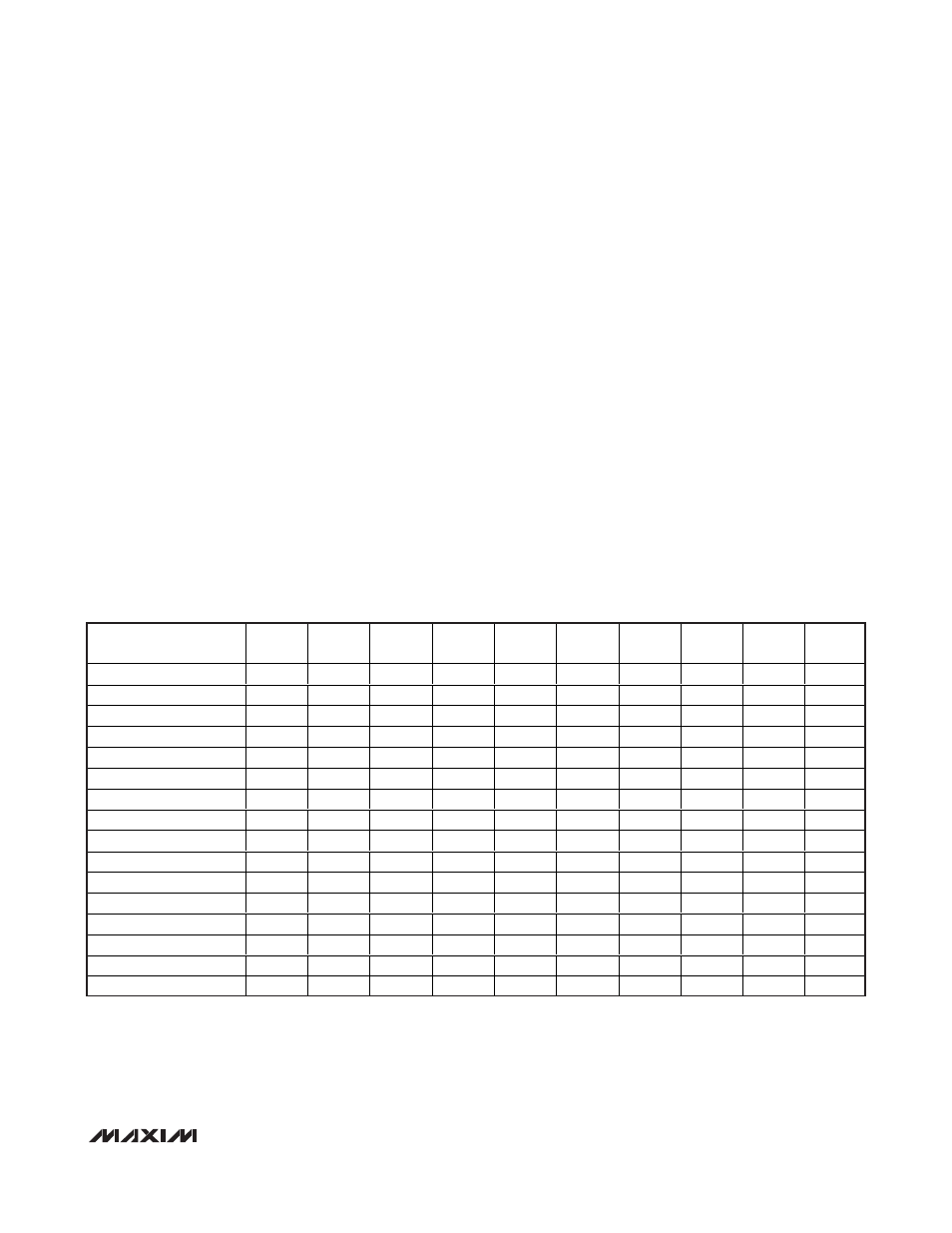
Mode Selection
The mode-select inputs M0, M1, and M2 determine
which interface protocol is selected (Table 1 for the
MAX13171E, Table 2 for the MAX13173E). The state of
the DCE/DTE input determines whether the transceivers
are configured as a DTE serial port or a DCE serial port.
The INVERT input on the MAX13173E changes the
DCE/DTE functionality regarding T4/T5 and R4/R5 only.
M0, M1, M2, INVERT, and DCE/DTE are internally
pulled up to V
L
to ensure logic-high if left unconnected.
If the M0, M1, and M2 mode inputs are all unconnect-
ed, the MAX13171E/MAX13173E enter no-cable mode.
The MAX13175E mode select inputs and DCE/DTE
input do not have an internal pullup to V
L
. They are
pulled logic-high if their mode-select inputs are tied to
the MAX13171E/MAX13173E’s mode select inputs.
Termination Modes
The termination networks in the MAX13175E can be set
to one of three modes, V.11, V.35, or high impedance.
MAX13171E
MODE NAME
M2
M1
M0
DCE/
DTE
T1
T2
T3
R1
R2
R3
Not Used (Default V.11)
0
0
0
0
V.11
V.11
Z
V.11
V.11
V.11
RS-530A
0
0
1
0
V.11
V.11
Z
V.11
V.11
V.11
RS-530
0
1
0
0
V.11
V.11
Z
V.11
V.11
V.11
X.21
0
1
1
0
V.11
V.11
Z
V.11
V.11
V.11
V.35
1
0
0
0
V.35
V.35
Z
V.35
V.35
V.35
RS-449/V.36
1
0
1
0
V.11
V.11
Z
V.11
V.11
V.11
V.28/RS-232
1
1
0
0
V.28
V.28
Z
V.28
V.28
V.28
No Cable
1
1
1
0
Z
Z
Z
Z
Z
Z
Not Used (Default V.11)
0
0
0
1
V.11
V.11
V.11
Z
V.11
V.11
RS-530A
0
0
1
1
V.11
V.11
V.11
Z
V.11
V.11
RS-530
0
1
0
1
V.11
V.11
V.11
Z
V.11
V.11
X.21
0
1
1
1
V.11
V.11
V.11
Z
V.11
V.11
V.35
1
0
0
1
V.35
V.35
V.35
Z
V.35
V.35
RS-449/V.36
1
0
1
1
V.11
V.11
V.11
Z
V.11
V.11
V.28/RS-232
1
1
0
1
V.28
V.28
V.28
Z
V.28
V.28
No Cable
1
1
1
1
Z
Z
Z
Z
Z
Z
Table 1. MAX13171E Mode Selection